
Numerical controller and method for determining look-ahead variable

a look-ahead variable and controller technology, applied in the field of numerical controllers, can solve the problems of difficult discovery of such errors and mistakes made by designers or the like in code input, and achieve the effect of easy discovery of errors

Active Publication Date: 2019-09-17
FANUC LTD
View PDF14 Cites 0 Cited by
  • Summary
  • Abstract
  • Description
  • Claims
  • Application Information

AI Technical Summary

Benefits of technology

The present invention provides a numerical controller and a method for determining variables that can help discover errors that might occur when inputting codes for pausing look-ahead or designating the variables for which look-ahead is to be paused. This makes it easy to discover and fix errors, improving the efficiency and accuracy of the programming process.

Problems solved by technology

Therefore, there are cases in which mistakes may occur by the designer or the like in relation to inputting of codes for pausing look-ahead, or in designating the variables for which look-ahead is to be paused.
Further, even if mistakes occur in designation of variables or in inputting of codes, discovery of such mistakes is difficult.

Method used


Image

  • Numerical controller and method for determining look-ahead variable
  • Numerical controller and method for determining look-ahead variable
  • Numerical controller and method for determining look-ahead variable

Examples


first embodiment

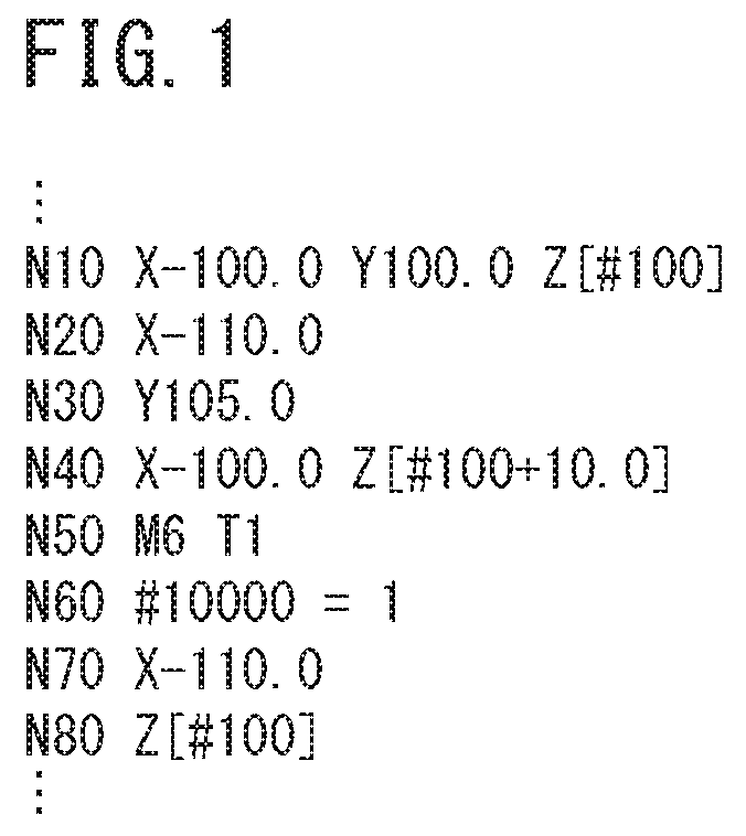
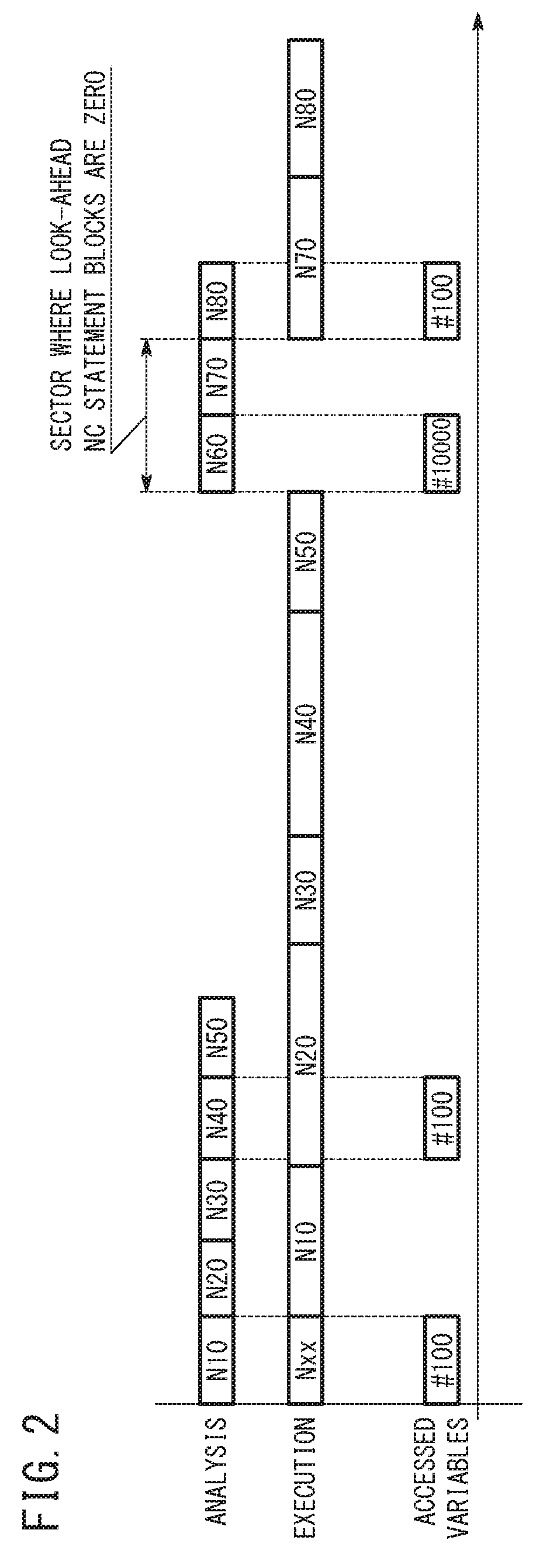
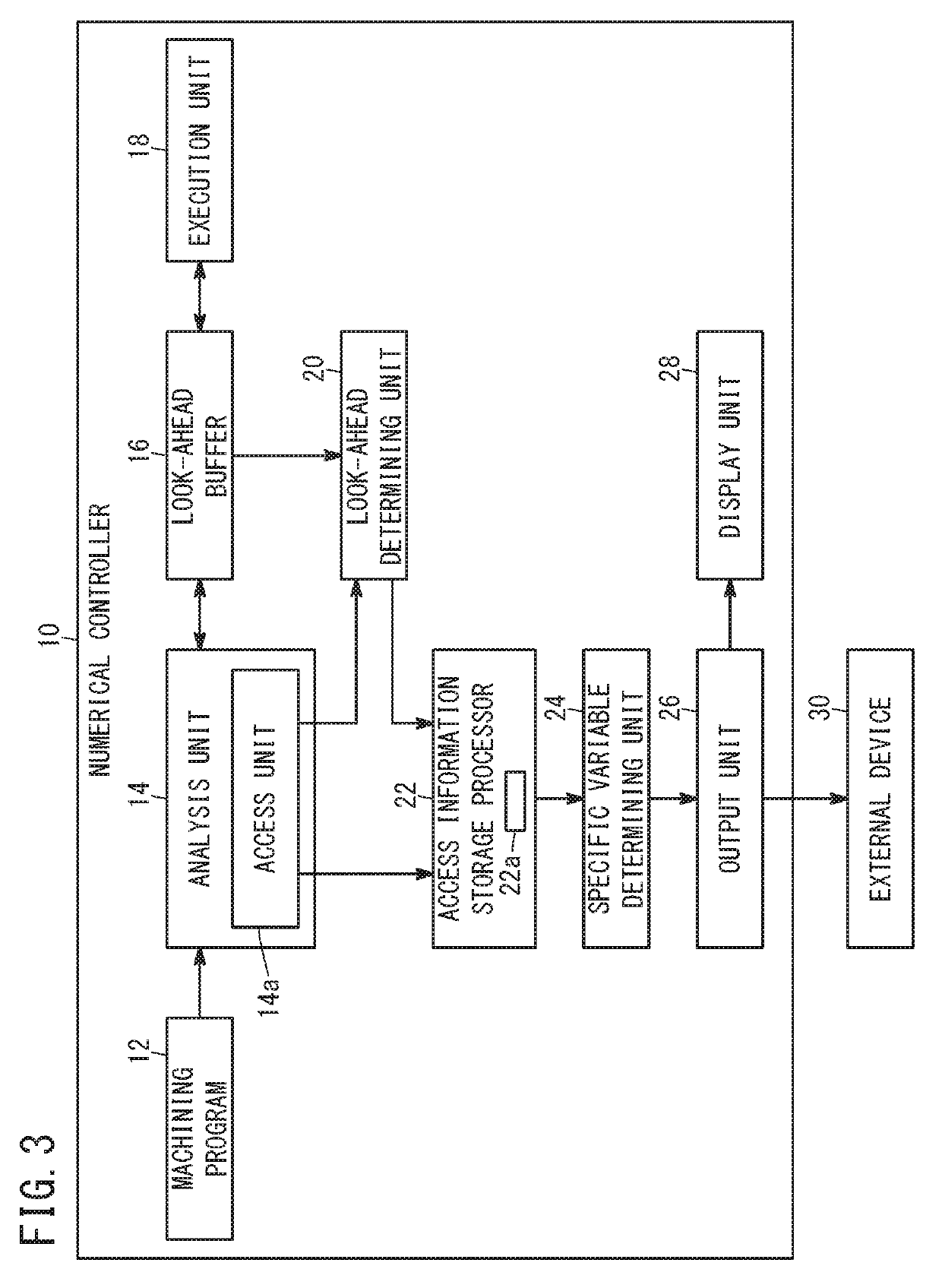
[0033]Initially, a description will be made concerning analysis of a machining program and execution of the machining program by a numerical controller 10 that controls a machine tool. FIG. 1 is a view showing an example of the machining program, and FIG. 2 is a view showing a timing chart of an analytical process and an execution process of the machining program shown in FIG. 1. The analysis and execution are performed by the numerical controller 10 shown in FIG. 3.

[0034]The machining program shown in FIG. 1 is made up from a plurality of blocks N10, N20, N30 . . . N70, N80 . . . . The N10 block, the N40 block, and the N80 block include variables having the variable number “#100”, and the N60 block includes a variable having the variable number “#10000”. Since the N60 block includes a variable (variable number “#10000”) that should not be accessed during look-ahead, before the N60 block, the N50 block is provided that includes a code therein to control (i.e., to pause) look-ahead. ...

second embodiment

[0058]FIG. 5 is a functional block diagram showing the configuration of a numerical controller 50 according to a second embodiment. The numerical controller 50 is constituted by a computer having a CPU and a memory, and by the CPU executing a program stored in the memory, the computer functions as the numerical controller 50 according to the second embodiment. The numerical controller 50 is equipped with a machining program 52, a predetermined program 54, a first access unit 56, a second access unit 58, an access information storage processor 60, a specific variable determining unit 62, an output unit 64, and a display unit 66. Moreover, an external device 68 is capable of communicating wirelessly or over wires with the output unit 64.

[0059]The machining program 52 and the predetermined program 54 are stored in a storage medium such as a memory or the like that constitutes hardware of the numerical controller 50. The machining program 52 is a program to carry out machining with resp...


PUM


Abstract

A numerical controller is equipped with an access unit configured to access variables included within a machining program at a time of analyzing the machining program, a look-ahead determining unit configured to determine whether or not the variables accessed by the access unit were accessed during look-ahead of the machining program, a specific variable determining unit configured to determine whether or not the variables determined to have been accessed during look-ahead by the look-ahead determining unit are specific variables, and an output unit configured to output at least one of numbers of the specific variables accessed during look-ahead and a time of accessing the specific variables during look-ahead, in the event that the variables accessed during look-ahead are determined to be the specific variables by the specific variable determining unit.

Description

CROSS-REFERENCE TO RELATED APPLICATION[0001]This application is based upon and claims the benefit of priority from Japanese Patent Application No. 2016-118749 filed on Jun. 15, 2016, the contents of which are incorporated herein by reference.BACKGROUND OF THE INVENTIONField of the Invention[0002]The present invention relates to a numerical controller having a look-ahead pausing function of a machining program as well as to a variable determining method used in the numerical controller.Description of the Related Art[0003]In a numerical controller, there are executed in parallel a look-ahead process of reading out and analyzing a machining program (NC program) block-by-block and storing the analysis results (execution data) therefor in a look-ahead buffer, and an execution process of executing the analysis results (execution data) that are stored in the look-ahead buffer.[0004]For this reason, a time lag occurs between the timing of the look-ahead process and the timing of the executi...

Claims


Application Information

Patent Timeline
Patent Type & Authority Patents(United States)
IPC IPC(8): G05B19/408
CPCG05B19/408G05B2219/35386G05B19/40937G05B2219/32161
Inventor KUBOTA, TOORU
Owner FANUC LTD
Learn More