
Closing valve unit for a cyclone

a technology of closing valve and cyclone, which is applied in the direction of mechanical equipment, flow apparatus, transportation and packaging, etc., can solve the problems of laborious and expensive, inconvenient to accomplish alterations, etc., and achieve the effects of saving space, simple and secure, and economical solution

Active Publication Date: 2017-02-21
ANDRIZ OY
View PDF4 Cites 0 Cited by
  • Summary
  • Abstract
  • Description
  • Claims
  • Application Information

AI Technical Summary

Benefits of technology

The closing valve unit invention helps in maintaining, repairing and replacing cyclones in a centrifugal cleaner group without causing any disturbance in the production process and without increasing the space requirement. The actuators are combined to prevent mistakes and save space. The flow channels and connecting members of the closing valve unit are designed to enhance its maintainability and flexibility of mounting. The use of slide type closing valves allows for easy replacement and the design of multiple flow channels in a compact space. The closing valve unit can be retrofit without causing any leakage or operational issues.

Problems solved by technology

In this situation it is not advantageous enough to accomplish alterations and mount separate closing valves in each connection between a channel of a group of centrifugal cleaners and their cyclones, since it is laborious and expensive.

Method used


Image

  • Closing valve unit for a cyclone
  • Closing valve unit for a cyclone
  • Closing valve unit for a cyclone

Examples


Embodiment Construction

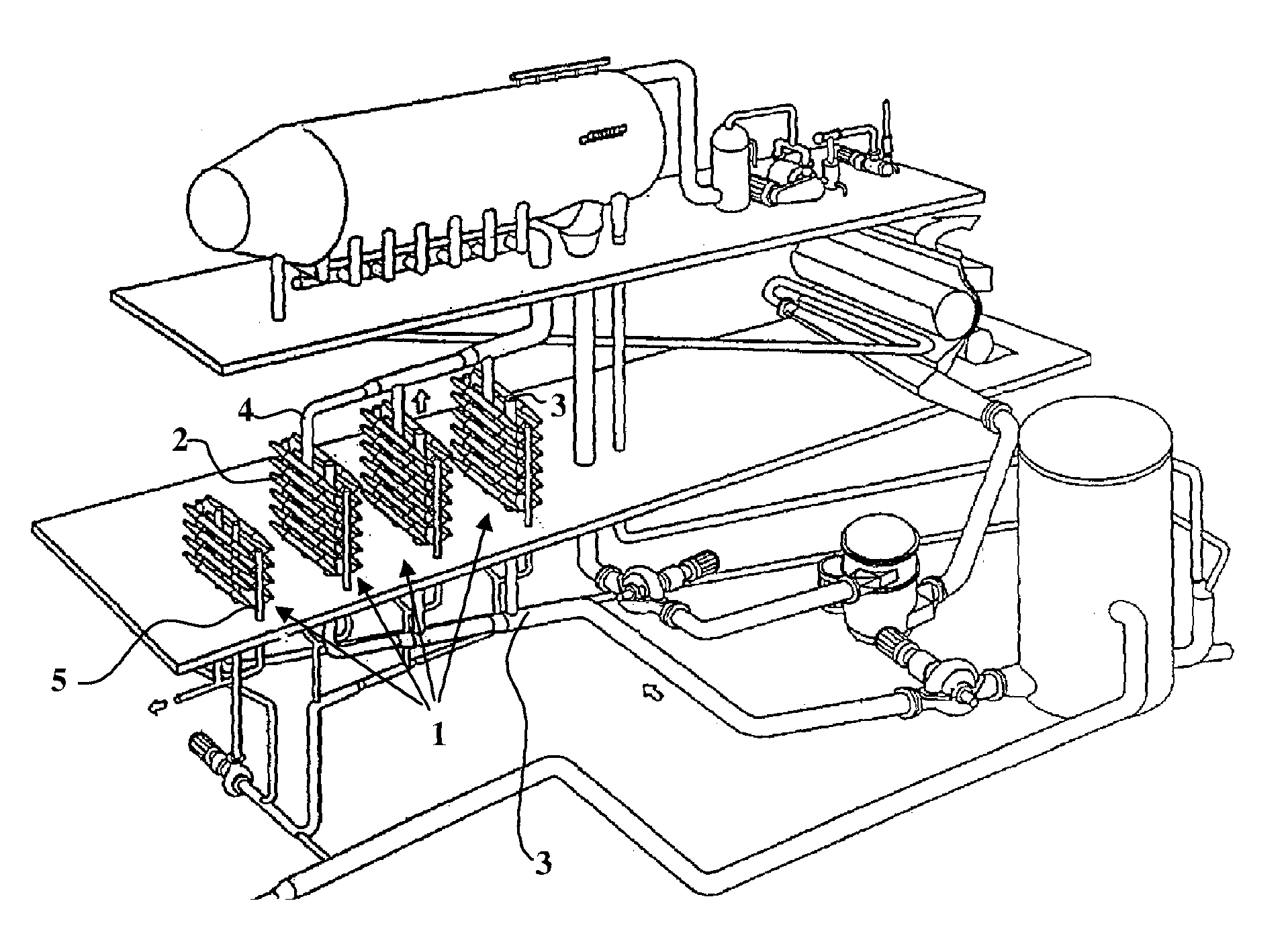
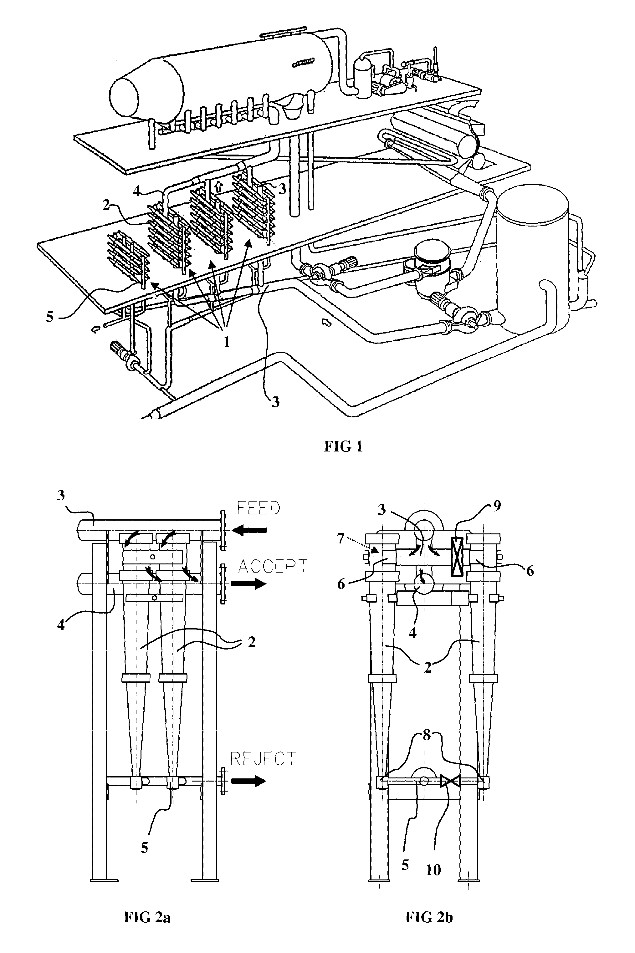
[0035]The centrifugal cleaner plant of FIG. 1 comprises several twin cyclones, which are packed as tightly as possible in several groups 1, whereto the cyclones 2 are connected to inlet, i.e. feed channels 3, outlet, i.e. accept channels 4 and reject channels 5. Additionally the figure illustrates examples of production apparatuses upstream and downstream of the cleaning stage. Typically the preceding and following processes are continuous and a good example is the approach system of a paper machine, which may comprise a considerably greater number of cyclones 2 and more tightly placed than in the exemplary figure.

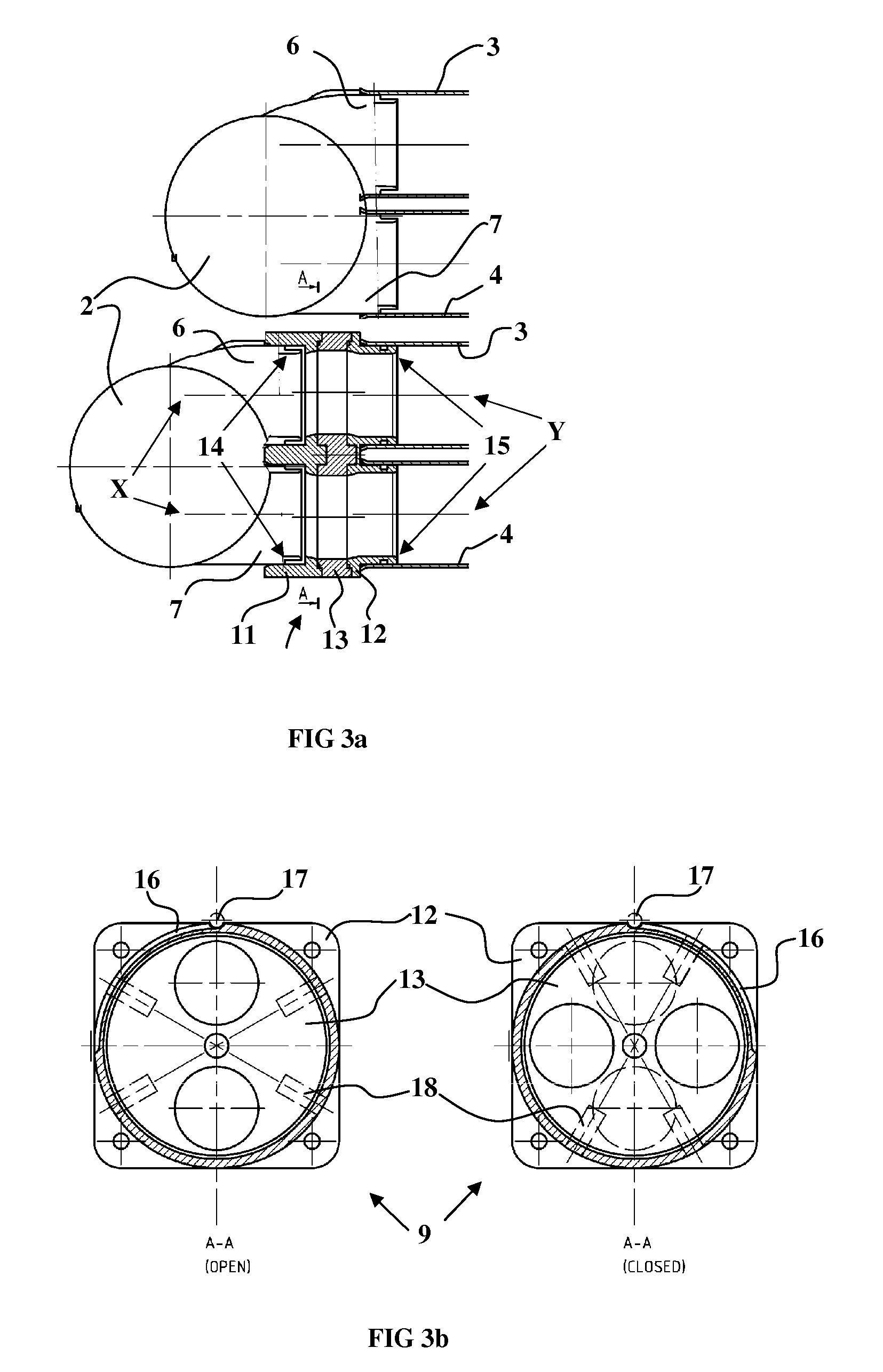
[0036]FIGS. 2a and 2b illustrate in more detail the connections between the centrifugal cleaner group and the cyclones. There a group of four cyclones is illustrated from two directions and a closing valve unit is connected to one of the cyclones. The central axes of the feed conduits 6 and accept conduits 7 of the cyclone 2 are directed crosswise with respect to the longi...


PUM


Abstract

A closing valve unit for a centrifugal cleaner arrangement including first and second connecting members configured to connect a cyclone to a centrifugal cleaner group, and a movable valve sandwiched between the first and second connecting members, the moveable valve including apertures commensurate with openings to feed and reject conduits of the cyclone and to openings to feed and reject conduits of the cyclone cleaner group, wherein the movable valve has a first position in which the apertures are aligned with the cyclone and cleaner group feed conduits and with the cyclone accept and cleaner group accept conduits, and a control element connected to the moveable valve and configured to move the moveable valve between the first position and the second positions.

Description

RELATED APPLICATIONS[0001]This application is the U.S. national phase of International Application No. PCT / FI 2012 / 050865 filed Sep. 6, 2012 which designated the U.S. and claims priority to FI 20115881 filed Sep. 7, 2011, the entire contents of each of which are hereby incorporated by reference.BACKGROUND OF INVENTION[0002]The present invention relates to arrangements for separating and cleaning gaseous and liquid substances with cyclones and especially treating liquid suspensions that are used in the production of paper and board.[0003]For purifying suspensions of the paper and pulp industry of coarser and / or finer impurities and dirt particles, mainly centrifugal cleaning apparatuses, i.e. hydrocyclones are used, or later, shorter, cyclones when reference is made to an individual cyclone.[0004]The through flow of fiber suspension is enormous in a conventional paper or pulp mill and correspondingly a large amount of cyclones are needed. A centrifugal cleaning arrangement may compri...

Claims


Application Information

Patent Timeline
IPC IPC(8): B04C11/00B04C3/06F16K11/074
CPCB04C11/00B04C3/06F16K11/074Y10T137/86533B04C5/24B04C5/28D21D5/24
Inventor IMMONEN, JARMOJARVINEN, MARITASUORTTI, SIMO
Owner ANDRIZ OY
Learn More