Quick-adjust tensioner

a technology of tensioner and torque adjustment, which is applied in the field of quick adjustment of tensioners, can solve the problems of multiple torque adjustments of a standard tensioner, affecting the stability of the supporting rod, and unable to disclose the resilience of the straps connecting the heads

Active Publication Date: 2019-10-01
AKERWORKS INC
View PDF26 Cites 2 Cited by
  • Summary
  • Abstract
  • Description
  • Claims
  • Application Information

AI Technical Summary

Benefits of technology

[0008]According to one embodiment of the present invention, a tensioner for a spool is provided. The tensioner includes a stop configured to attach to a rod holding a spool. Static friction holds the stop in one location on the rod. The tensioner also includes a foot configured to press with a second force against the spool. The foot pressing against the spool creates a resistance against the spool turning, thus creating a braking torque. The foot also acts in conjunction with the stop to keep the spool from changing position on the rod.
[0010]The distance between the stop and the foot is inversely related to the second force of the foot against the spool. The second force of the foot against the spool is directly related to the braking torque caused by the foot resisting the spool turning. Thus, the user moves the stop closer to the foot in order to increase the force of the foot on the spool and increase the braking torque. To reduce the braking torque, the user moves the stop farther away from the foot. Thus, the user is able to fine-tune the braking torque of the tensioner on the spool, and increase or decrease the tension on the line.
[0013]In some embodiments, the stop includes auxillary holes. The auxiliary holes are parallel to the first aperture. The auxiliary holes contract in response to the first aperture being expanded. Thus, the effective elasticity of the first aperture is increased by the ability of the material surrounding the first aperture to expand into the auxiliary holes.
[0016]The tensioner is placed upon the rod by placing the guide's second aperture on the rod and then the stop's first aperture on the rod. The stop is slid down the rod until the foot contacts the top surface of the spool and the biasing member bends. The stop is then adjusted closer or further from the foot to bend the biasing member the desired amount such that the proper braking torque of the foot on the spool is achieved. In some embodiments, the biasing member is capable of bending sufficiently without damage even when the stop and foot are pressed against each other.
[0018]In one embodiment, the tensioner is part of a line dispensing system capable of dispensing one or multiple lines. In another embodiment, the tensioner is part of a fishing reel. In another embodiment, the tensioner is part of a twine dispenser. In another embodiment, the tensioner is part of a portable ribbon dispenser. In another embodiment, multiple tensioners are part of a system of multiple rods and spools such that the braking effect of the tensioners on the material being unspooled is cumulative.
[0024]In one embodiment, the tensioner is stored in a recess. The recess is configured to receive the tensioner such that the biasing member is bent, and the foot and stop bias against the sides of the recess and hold the tensioner in place. Thus, the tensioner remains stored in the recess even when the recess is moved, tilted, or turned over. The first and second apertures are non-aligned in the recess in order to mitigate the long-term effect of storing the biasing member in a bent position.

Problems solved by technology

However, standard tensioners do not allow the user to quickly remove the tensioner or to quickly adjust the amount of braking torque that the tensioner exerts on the spool.
Moreover, multiple torque adjustments of an standard tensioner will eventually wear out both the tensioner and the supporting rod upon which is it situated.
Arjomand does not disclose that the straps connecting the heads are resilient.

Method used


Image

  • Quick-adjust tensioner
  • Quick-adjust tensioner
  • Quick-adjust tensioner

Examples


embodiment 100

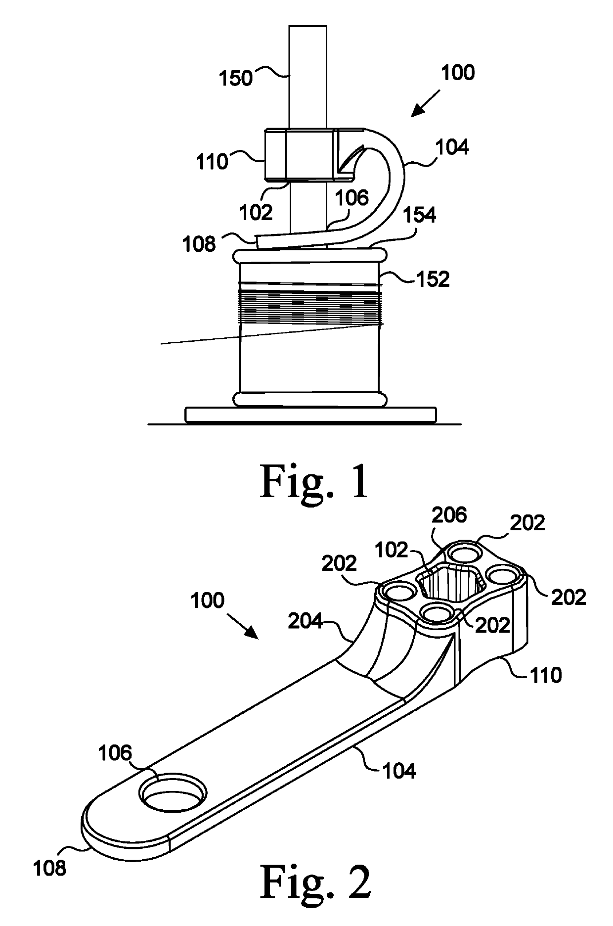
[0048]In the displayed embodiment 100, the biasing member 104 is resilient and has a bias to return to a straight position. Thus, reducing the distance between the stop 110 and the foot 108 will increase the spring force of the biasing member 104, thereby creating a greater braking torque of the foot 108 on the spool 152. Likewise, increasing the distance between the stop 110 and the foot 108 will reduce the force of the biasing member 104 pressing the foot 108 downward, and the braking torque on the spool 152 will be reduced. Thus, the user predetermines, in one way, the braking torque on the spool 152 by fixing the distance between the stop 110 and the foot 108.

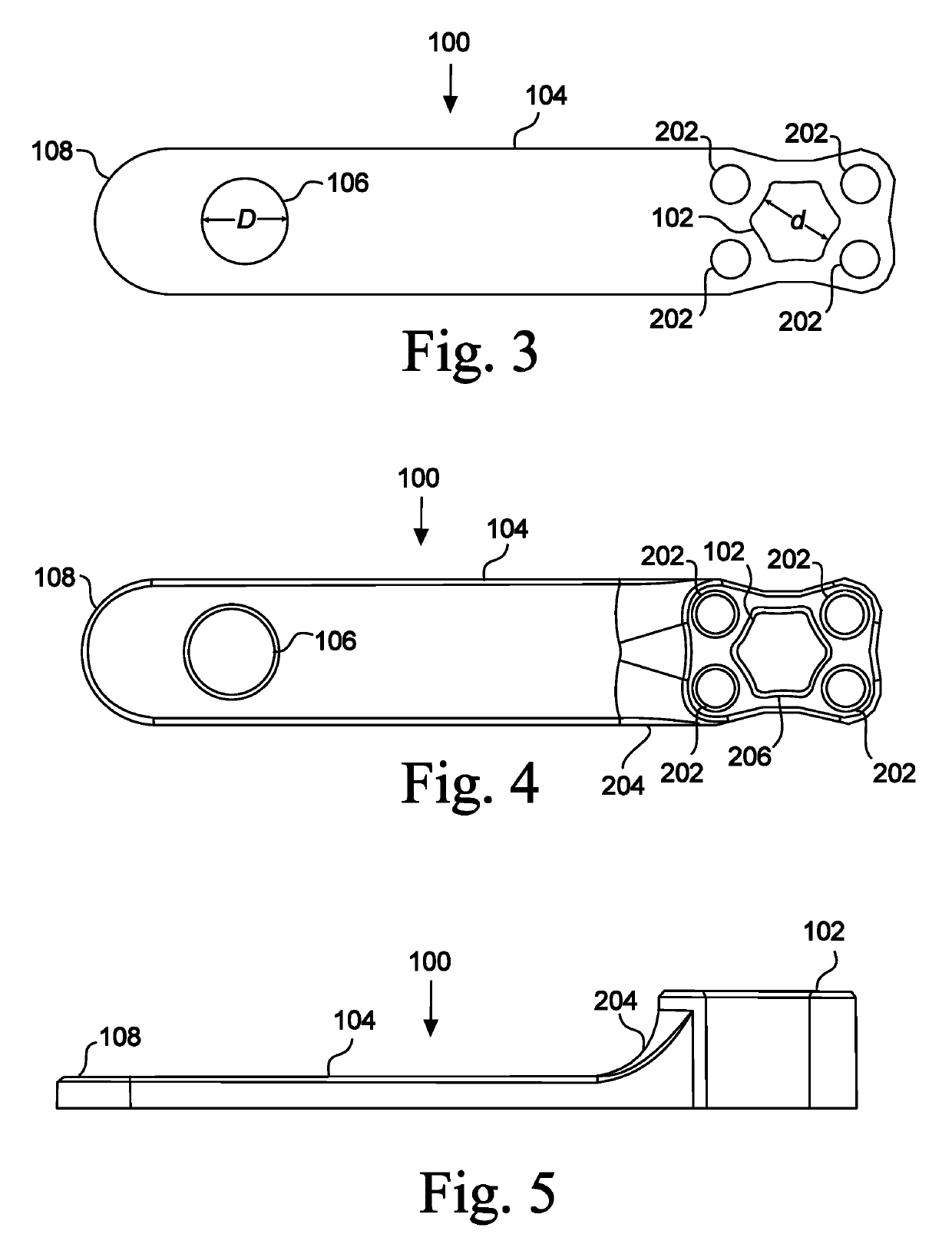
[0049]FIGS. 2, 3, 4, and 5 illustrate an embodiment of the tensioner 100 in a rest position. In the displayed embodiment 100, the biasing member 104 is straight and flat when in a rest position. In other embodiments, the biasing member 104 is at rest in a curved position. In other embodiments, the biasing member 104 is in a...

embodiment 700

[0070]In FIG. 7, the stop 110 of the tensioner 100 grips the drive shaft 702 with a first static torque (i.e., a force resisting being rotated relative to the shaft). The biasing member 104 is pressing the foot 108 of the tensioner 100 against the spin sleeve 704. The downward force of the foot 108 on the spin sleeve 704 creates a second static torque holding the foot 108 and spin sleeve 704 in a fixed relative position. In the displayed embodiment 700, ridges 712 extend from the top of the spin sleeve 704 to catch against the foot 108 for extra traction. The second static torque is adjustable by increasing or decreasing the distance between the stop 110 and foot 108, thereby changing the force of the biasing member 104 against the foot 108. The maximum possible first static torque between the stop 110 and drive shaft 702 is greater than the second static torque between the foot 108 and spin sleeve 704—that is, if the drive shaft 702 and spin sleeve 704 were rotated in opposite dire...


PUM


Abstract

Quick-adjust tensioner that exerts a braking torque on a spool. The tensioner includes a stop configured to fit onto a rod supporting the spool. The location of the stop on the rod is adjustable by the user. The stop is connected to a foot by a biasing member. The biasing member presses the foot against the spool to create a braking torque on the spool. The force of the biasing member on the foot is predetermined by adjusting the distance between the stop and the foot, thereby adjusting the foot's braking torque on the spool.

Description

CROSS-REFERENCE TO RELATED APPLICATIONS[0001]This application claims the benefit of provisional Application No. 62 / 412,320, filed Oct. 25, 2016.STATEMENT REGARDING FEDERALLY SPONSORED RESEARCH OR DEVELOPMENT[0002]Not Applicable.BACKGROUND1. Field of Invention[0003]This invention pertains to tensioners. More particularly, this invention pertains to quick-adjust tensioners for spooling materials.2. Description of the Related Art[0004]Tensioners are commonly used to regulate the speed at which spooled materials are dispensed, and to tauten the material leaving the spool. A tensioner creates a braking torque on the spool, thereby counteracting the pull of the thread or other spooled material on the spool. Many tensioners create the braking torque with a fixed object pressed against a spool end. The braking torque creates kinetic friction between the immovable object and the spool. The braking torque also creates static friction between the immovable object and the spool, thereby allowin...

Claims


Application Information

Patent Timeline
Patent Type & Authority Patents(United States)
IPC IPC(8): B65D63/14B65H75/44B65H59/04B65H49/28D05B43/00B65H54/54
CPCB65H49/28D05B43/00B65H59/04B65H75/4444B65D63/14B65H2701/31B65H54/54
Inventor AKERMAN, ADAN
Owner AKERWORKS INC
Why Eureka
Try Eureka