Quick-adjust Tensioner

Active Publication Date: 2018-04-26
AKERWORKS INC
View PDF22 Cites 1 Cited by
  • Summary
  • Abstract
  • Description
  • Claims
  • Application Information

AI Technical Summary

Benefits of technology

The present invention provides a tensioner for a spool that can be used in various applications such as line dispensing or fishing reels. The tensioner includes a stop and a foot that work together to create a braking torque that prevents the spool from changing position on the rod. The distance between the stop and the foot can be adjusted to control the braking torque and tension on the line. The stop includes auxiliary holes that allow for increased elasticity and can be slid down the rod to adjust the tension. The tensioner can be stored in a recess and remains in place even when the recess is moved or turned over. The technical effects of the invention are improved control and adjustability of tension on the line, as well as improved storage and protection of the tensioner.

Problems solved by technology

However, standard tensioners do not allow the user to quickly remove the tensioner or to quickly adjust the amount of braking torque that the tensioner exerts on the spool.
Moreover, multiple torque adjustments of an standard tensioner will eventually wear out both the tensioner and the supporting rod upon which is it situated.
Arjomand does not disclose that the straps connecting the heads are resilient.

Method used


Image

  • Quick-adjust Tensioner
  • Quick-adjust Tensioner
  • Quick-adjust Tensioner

Examples


embodiment 100

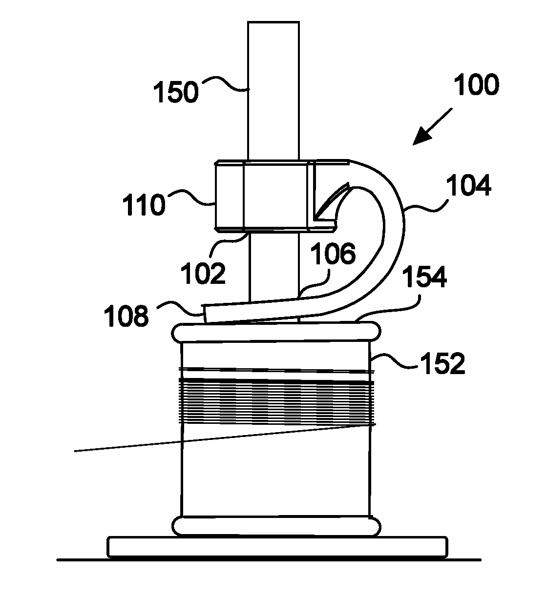
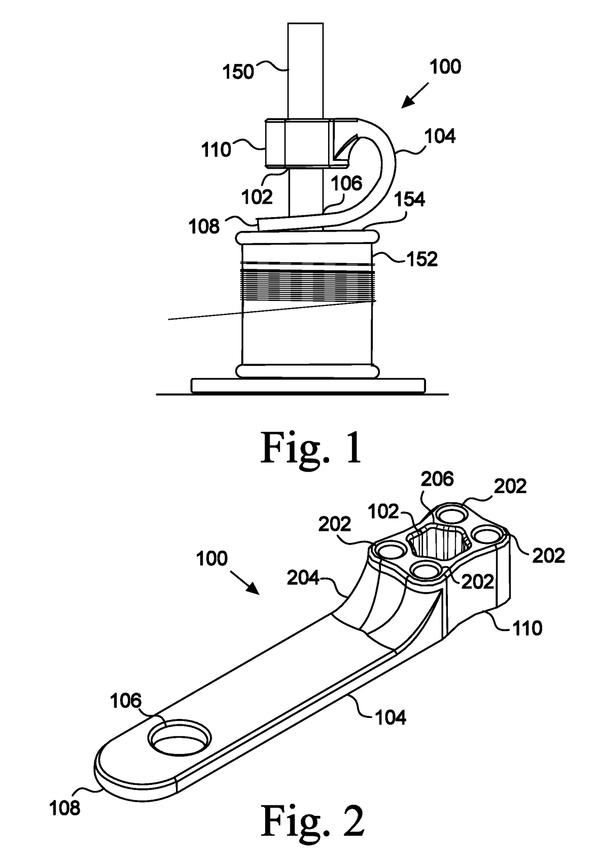
[0048]In the displayed embodiment 100, the biasing member 104 is resilient and has a bias to return to a straight position. Thus, reducing the distance between the stop 110 and the foot 108 will increase the spring force of the biasing member 104, thereby creating a greater braking torque of the foot 108 on the spool 152. Likewise, increasing the distance between the stop 110 and the foot 108 will reduce the force of the biasing member 104 pressing the foot 108 downward, and the braking torque on the spool 152 will be reduced. Thus, the user predetermines, in one way, the braking torque on the spool 152 by fixing the distance between the stop 110 and the foot 108.

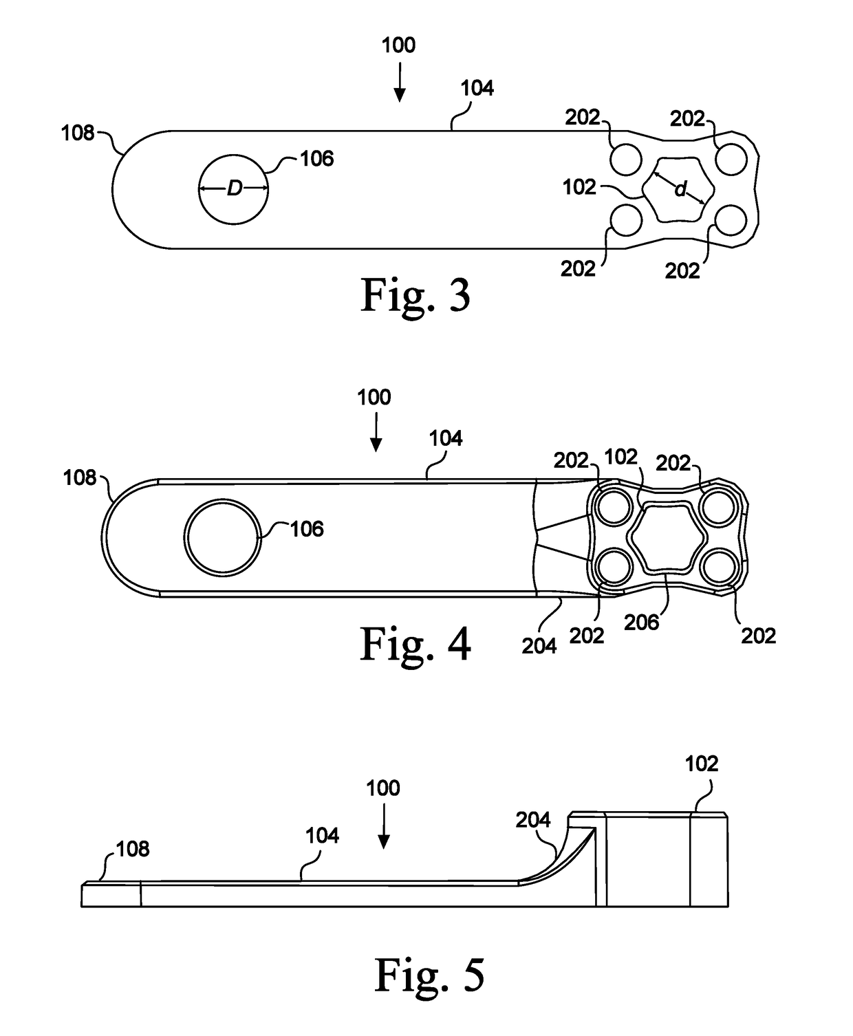
[0049]FIGS. 2, 3, 4, and 5 illustrate an embodiment of the tensioner 100 in a rest position. In the displayed embodiment 100, the biasing member 104 is straight and flat when in a rest position. In other embodiments, the biasing member 104 is at rest in a curved position. In other embodiments, the biasing member 104 is in a...

embodiment 700

[0070]In FIG. 7, the stop 110 of the tensioner 100 grips the drive shaft 702 with a first static torque (i.e., a force resisting being rotated relative to the shaft). The biasing member 104 is pressing the foot 108 of the tensioner 100 against the spin sleeve 704. The downward force of the foot 108 on the spin sleeve 704 creates a second static torque holding the foot 108 and spin sleeve 704 in a fixed relative position. In the displayed embodiment 700, ridges 712 extend from the top of the spin sleeve 704 to catch against the foot 108 for extra traction. The second static torque is adjustable by increasing or decreasing the distance between the stop 110 and foot 108, thereby changing the force of the biasing member 104 against the foot 108. The maximum possible first static torque between the stop 110 and drive shaft 702 is greater than the second static torque between the foot 108 and spin sleeve 704—that is, if the drive shaft 702 and spin sleeve 704 were rotated in opposite dire...


PUM


Abstract

Quick-adjust tensioner that exerts a braking torque on a spool. The tensioner includes a stop configured to fit onto a rod supporting the spool. The location of the stop on the rod is adjustable by the user. The stop is connected to a foot by a biasing member. The biasing member presses the foot against the spool to create a braking torque on the spool. The force of the biasing member on the foot is predetermined by adjusting the distance between the stop and the foot, thereby adjusting the foot's braking torque on the spool.

Description

CROSS-REFERENCE TO RELATED APPLICATIONS[0001]This application claims the benefit of provisional Application No. 62 / 412,320, filed Oct. 25, 2016.STATEMENT REGARDING FEDERALLY SPONSORED RESEARCH OR DEVELOPMENT[0002]Not Applicable.BACKGROUND1. Field of Invention[0003]This invention pertains to tensioners. More particularly, this invention pertains to quick-adjust tensioners for spooling materials.2. Description of the Related Art[0004]Tensioners are commonly used to regulate the speed at which spooled materials are dispensed, and to tauten the material leaving the spool. A tensioner creates a braking torque on the spool, thereby counteracting the pull of the thread or other spooled material on the spool. Many tensioners create the braking torque with a fixed object pressed against a spool end. The braking torque creates kinetic friction between the immovable object and the spool. The braking torque also creates static friction between the immovable object and the spool, thereby allowin...

Claims


Application Information

Patent Timeline
IPC IPC(8): B65D63/14
CPCB65D63/14D05B43/00B65H2701/31B65H54/54B65H49/28B65H59/04B65H75/4444
Inventor AKERMAN, ADAN
Owner AKERWORKS INC
Why Eureka
Try Eureka