
Mobile machine

a mobile machine and motor technology, applied in the direction of steering parts, non-deflectable wheel steering, vehicle components, etc., can solve the problems of crane tilting, ground failure, ground present under, etc., to reduce ground pressure, increase the spectrum of admissible subsoils, and reduce the effect of ground pressur

Active Publication Date: 2019-10-08
LIEBHERR WERK NENZING
View PDF14 Cites 0 Cited by
  • Summary
  • Abstract
  • Description
  • Claims
  • Application Information

AI Technical Summary

Benefits of technology

The objective of this patent is to reduce the pressure that a mobile machine applies to the ground at the site of use. This helps to increase the range of uses for the machine, as it can work on a wider range of soil conditions. Examples of mobile machines include cranes and piling and drilling rigs. The technical effect of this invention is to allow for more flexibility and efficiency in the use of mobile machines.

Problems solved by technology

In extreme cases, ignoring or underestimating this high pressure variation or also the high ground pressures in general leads to accidents due to ground failure.
In this case, the ground present under the crawler crane yields due to the too high ground pressure and in the unfavorable case makes the crawler crane tilt towards one side.
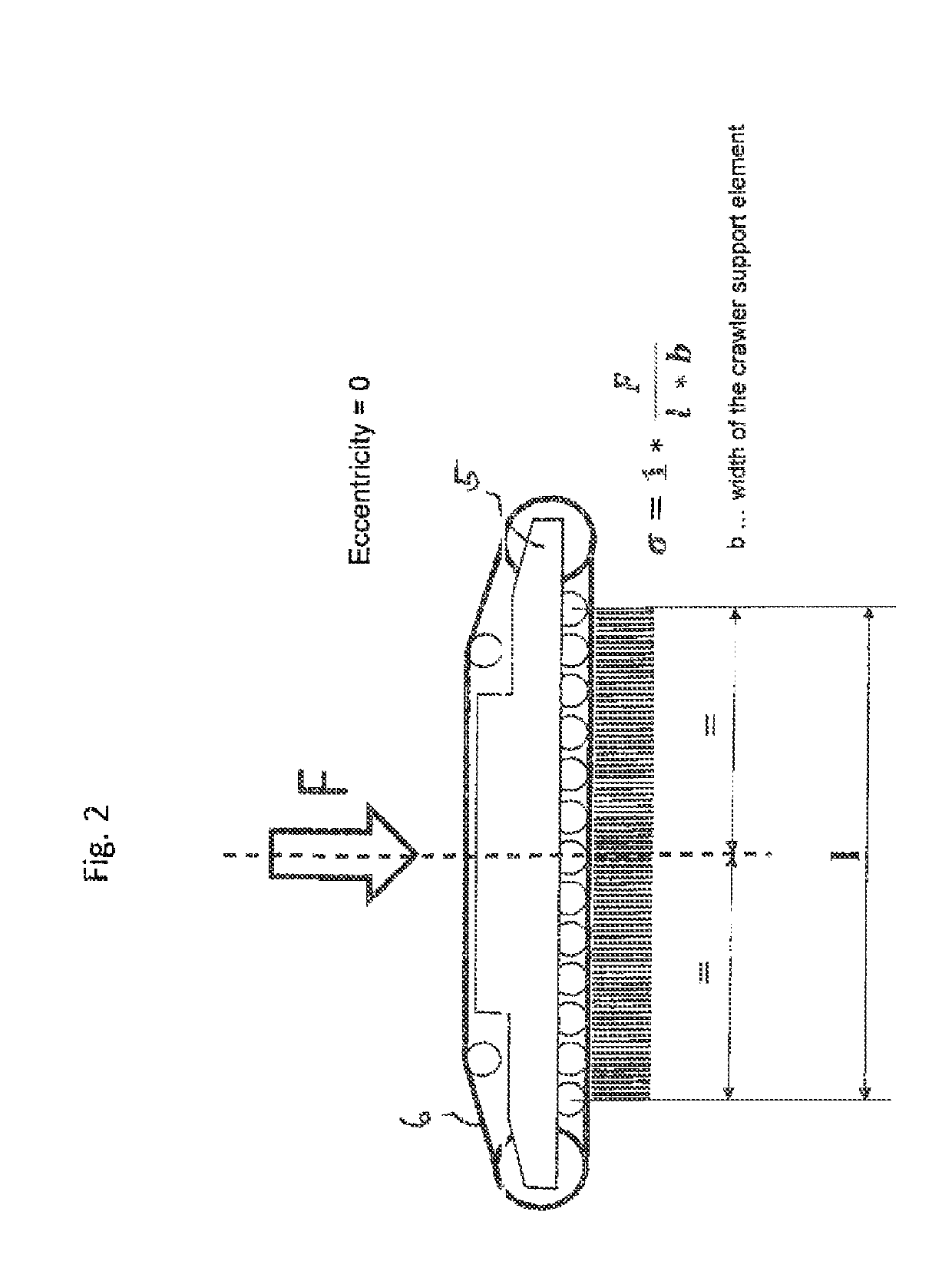
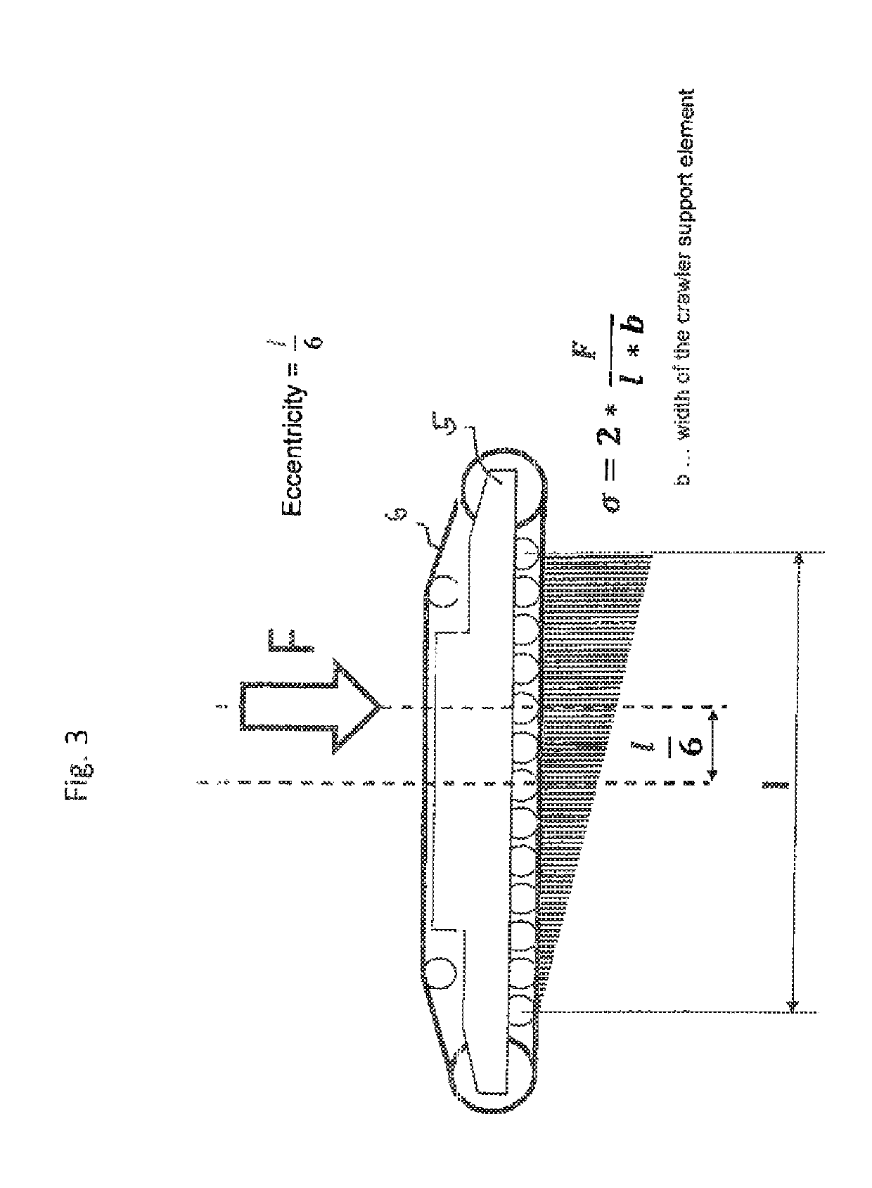
When the eccentricity of the center of pressure is greater than one sixth of the crawler standing surface, this even leads to the fact that a part of the standing surface of the crawler lifts off, which leads to a further increase of the maximum ground pressure.
In this implementation it is disadvantageous that the construction variants proposed in the prior art are very costly and expensive.
In addition, the entire weight of the undercarriage is increased considerably, which involves additional disadvantages with regard to the transport and the assembly time of the crane.
Moreover, the support arms protruding to the outside from the crawler crane require additional space, which is not easily available at any site of use.

Method used


Image

  • Mobile machine
  • Mobile machine
  • Mobile machine

Examples


Embodiment Construction

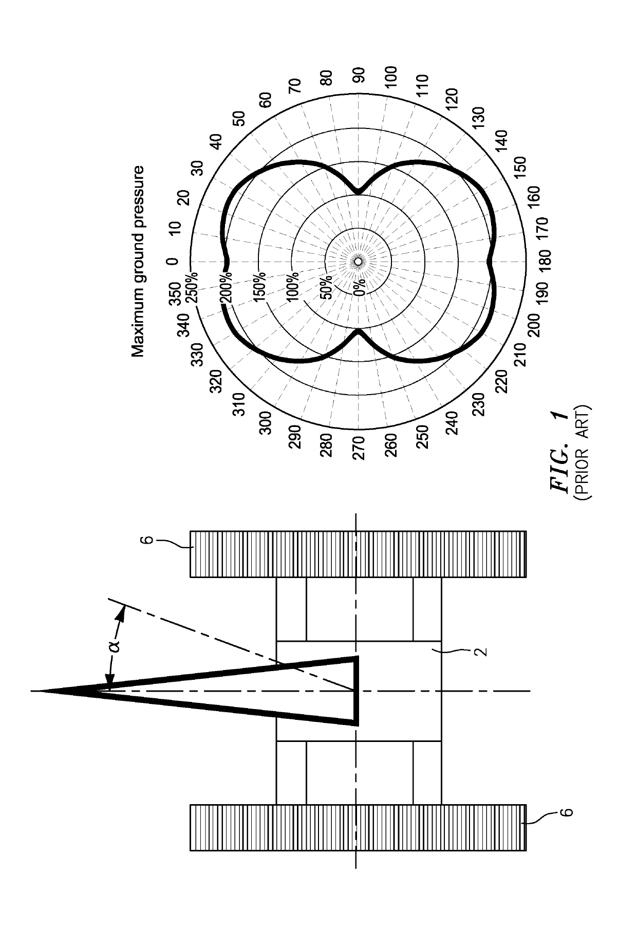
[0038]FIG. 1 shows a representation which illustrates the maximum ground pressure, i.e. the pressure which is exerted on the ground by the crawler crane placed thereon. On the left side it can be seen that the crane configuration present here is one from the prior art. The triangle arranged parallel to the two crawler supports points towards the front and indicates an alignment of the crane boom at 0°. The 0° position here represents an alignment of the crane boom into an orientation towards the front parallel to the two crawler supports. A rotation of the boom about an axis vertical to the ground plane describes the boom angle α, wherein for each boom angle α a specific ground pressure value is represented in the diagram shown on the right.

[0039]It can be seen here that the minimum of the maximum ground pressure is reached at a deviation of 90° about the alignment to the front (0°) or to the rear (180°). This results from the fact that the load occurring thereby is applied transver...


PUM


Abstract

The present invention relates to a mobile machine, in particular a crawler crane, comprising: an undercarriage with a tracklaying gear, and an uppercarriage which is rotatably mounted with respect to the undercarriage, wherein the tracklaying gear includes two crawler supports aligned parallel to each other, along whose longitudinal direction a crawler chain each is movably arranged, wherein one cantilever arm each is provided on the inner sides of the crawler supports facing each other, and at the distal end of the respective cantilever arm a support cylinder is arranged.

Description

BACKGROUND OF THE INVENTION[0001]The present invention relates to a mobile machine and in particular deals with the enormous ground pressure obtained under the load of a mobile machine, for example a crawler crane.[0002]The high ground pressure obtained under the load of a mobile machine is regarded as a decisive factor which is to be clarified prior to an operation of a mobile machine. In particular with a boom orientation of a crawler crane which is parallel to the longitudinal direction of the undercarriage or deviates therefrom by the angular amount of + / −30°, ground pressures occur which are two to three times as large as is the case with a boom orientation transversely to the undercarriage (and thus also transversely to the crawler supports). In extreme cases, ignoring or underestimating this high pressure variation or also the high ground pressures in general leads to accidents due to ground failure. In this case, the ground present under the crawler crane yields due to the t...

Claims


Application Information

Patent Timeline
Patent Type & Authority Patents(United States)
IPC IPC(8): B66C23/78B62D55/084B62D11/20B66C23/76B66C23/36B66C23/80
CPCB66C23/36B66C23/80B66C23/76B62D11/20B66C23/78B62D55/084
Inventor MIETSCHNIG, WALTER
Owner LIEBHERR WERK NENZING
Learn More