
Closed loop 3D printing

a closed loop, 3d printing technology, applied in the field of 3d printing, can solve the problems of limited control of interfacial healing, poor healing and weak parts, and the possibility of changing the temperature, so as to improve the weld quality of the component printed

Inactive Publication Date: 2019-10-15
IOWA STATE UNIV RES FOUND
View PDF3 Cites 4 Cited by
  • Summary
  • Abstract
  • Description
  • Claims
  • Application Information

AI Technical Summary

Benefits of technology

[0008]Therefore, it is a primary object, feature, and / or advantage of the invention to improve on and / or overcome the deficiencies in the art.
[0009]It is another object, feature, and / or advantage of the invention to vary the temperature of an extruder filament of a 3D printing system to control part quality.
[0010]It is yet another object, feature, and / or advantage of the invention to heat the filament to a temperature based upon substrate temperature.
[0011]It is still another object, feature, and / or advantage of the invention to determine the substrate temperature by model and / or thermal imaging device or system.
[0012]It is a further object, feature, and / or advantage of the invention to provide an additional heating element to preheat a substrate to an ideal welding temperature for 3D printing.
[0013]It is still a further object, feature, and / or advantage of the invention to provide a method of 3D printing that improves the weld quality of the component printed.

Problems solved by technology

Because the processing parameters remain constant, there is limited control of the interfacial healing.
If the filament's temperature is too low, a lack of fusion may result in poor healing and weak parts.
However, because of thermal inertia of the metal extrusion die, it is not possible to vary the temperature fast enough to allow weld quality to be controlled.

Method used


Image

  • Closed loop 3D printing
  • Closed loop 3D printing
  • Closed loop 3D printing

Examples


Embodiment Construction

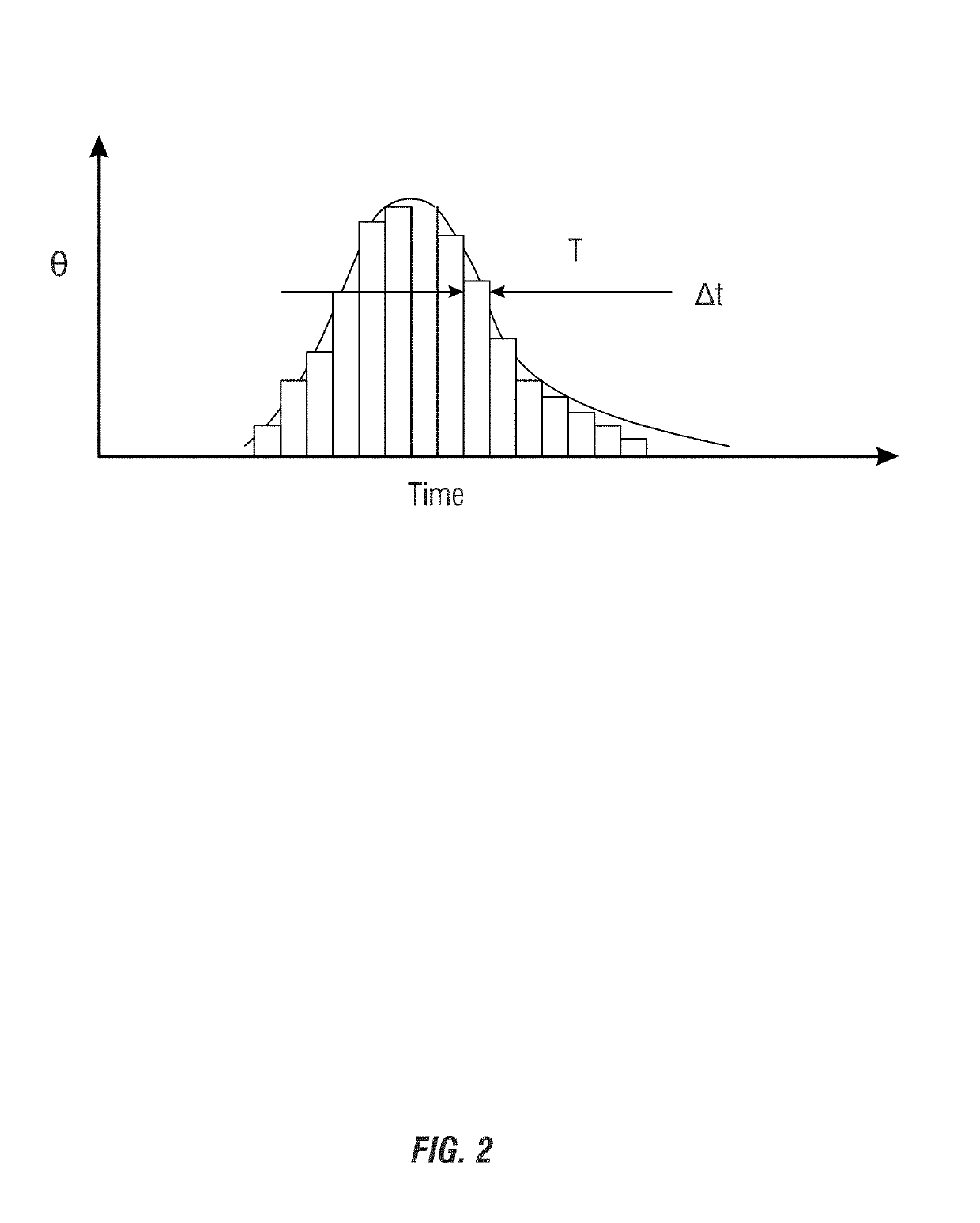
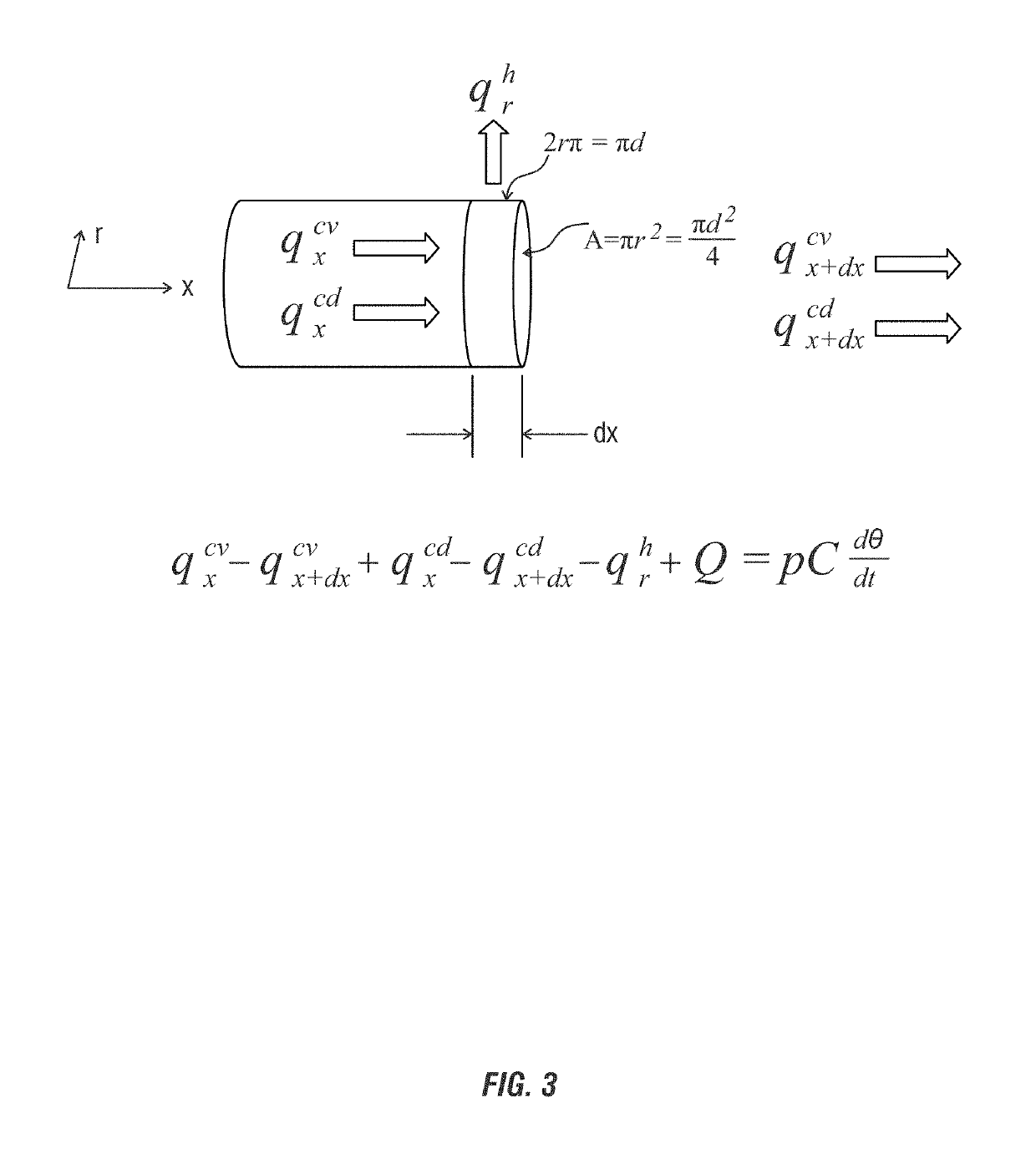
[0031]The present disclosure is directed towards an apparatus, system, and / or method of 3D printing that provides for greater control in the heat of a filament that is added to a substrate. Controlling the heat of the filament will provide for optimal welding temperature between the filament and the substrate, which will result in a higher quality weld between the elements. As will be understood, the temperature of 3D printing has been shown, through models and testing, to be the biggest factor in achieving such a high quality weld. As previously disclosed, welding / healing of two polymer interfaces occurs either quickly at a relatively high temperature, or slowly at a relatively low temperature, because interfacial healing is a diffusion process. By using Einstein's diffusion equation, where D is the diffusion coefficient, it is possible to show that healing is related to time to a power of ¼, such that X˜t1 / 4. If it is assumed that intermolecular diffusion and healing are proportio...


PUM

PropertyMeasurementUnit
diameteraaaaaaaaaa
velocityaaaaaaaaaa
wavelengthaaaaaaaaaa

Abstract

To better control part quality of 3D printed parts, the temperature of an extruder filament using a secondary heat source is provided. A heat source, such as an infrared heat source, can be used to heat the filament of a 3D printer to the optimum temperature that will enhance welding of the filament to a substrate that it is being printed on or to. Such an optimum temperature can be based upon, in part, the temperature of the substrate. A controller or other intelligent control can be used to receive temperature readings of the substrate and / or filament and then can adjust the temperature of the heating source to optimize the temperature of the filament to better combine the filament to the substrate.

Description

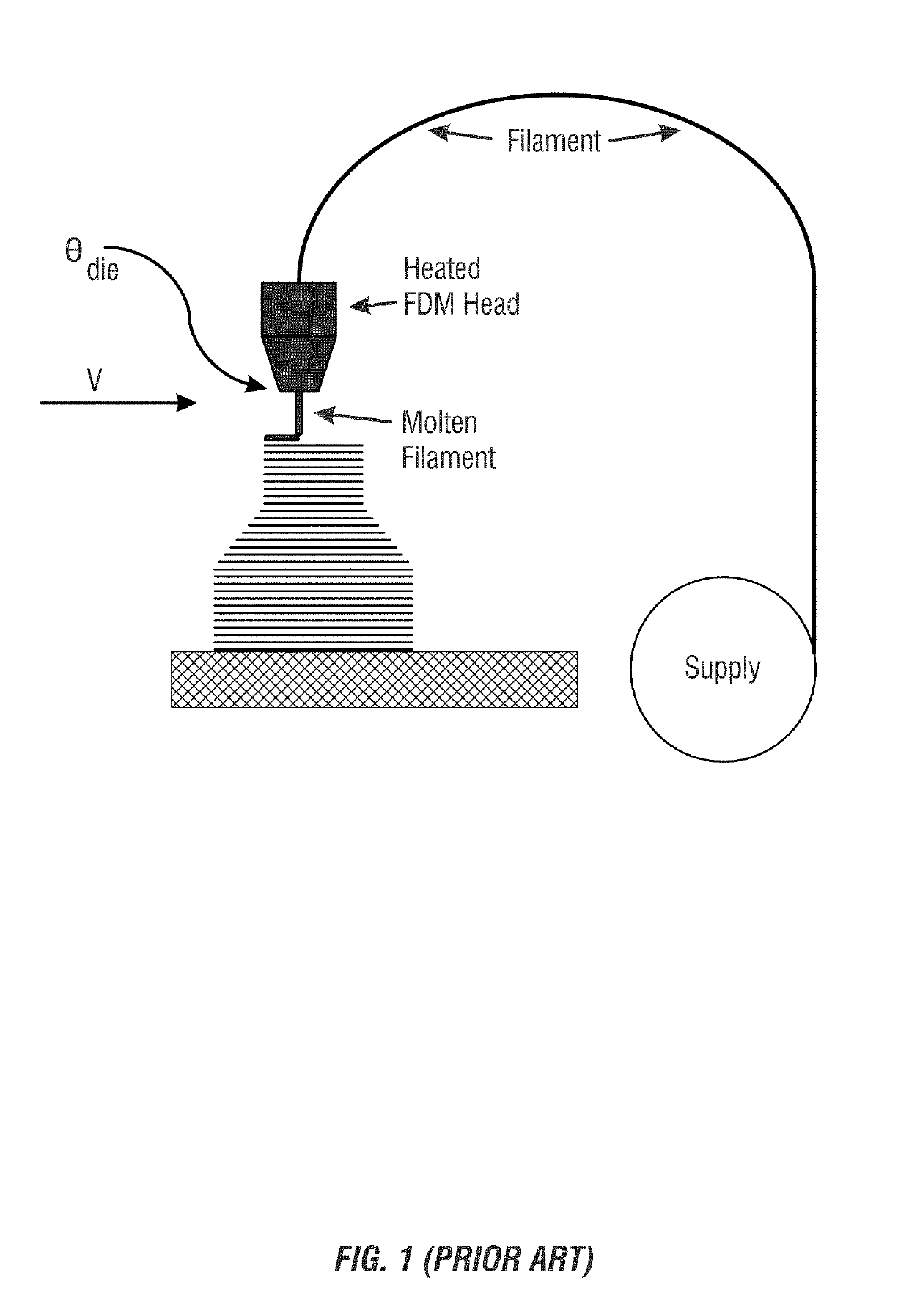
CROSS-REFERENCE TO RELATED APPLICATIONS[0001]This application claims priority under 35 U.S.C. § 119 to Provisional Application No. 62 / 234,394, filed on Sep. 29, 2015, the contents of which are hereby incorporated by reference in their entirety.FIELD OF THE INVENTION[0002]The disclosure relates generally to the field of 3D printing. More particularly, but not exclusively, the disclosure is directed towards fused deposition modeling, and the use of rapid temperature control to optimize the interfacial heating time and temperature during fusion.BACKGROUND OF THE INVENTIONS[0003]Currently, 3D printing, and in particular fused deposition modeling (FDM), employ constant extrusion temperature (θdie) and head velocity (V), as shown in FIG. 1. The level of control currently available in FDM is similar to that in other 3D printing techniques, such as laser sintering.[0004]Because the processing parameters remain constant, there is limited control of the interfacial healing. When the filament,...

Claims


Application Information

Patent Timeline
Patent Type & Authority Patents(United States)
IPC IPC(8): B29C64/106B29C35/02B29C35/08B33Y10/00B33Y30/00B29C64/386B33Y50/02B29K105/00
CPCB29C35/0288B29C35/0805B29C2035/0822B29C2035/0838B33Y10/00B33Y30/00B33Y50/02B29C64/106B29C64/118B29C64/295B29C64/393B29K2105/0067
Inventor GREWELL, DAVID
Owner IOWA STATE UNIV RES FOUND
Learn More