Image processing apparatus and method of controlling the same

a technology of image processing and control apparatus, applied in the direction of image analysis, image enhancement, details involving processing steps, etc., can solve the problems of unnatural color, unnatural color, and a certain amount of error, and achieve the effect of suppressing image degradation of an obj

Active Publication Date: 2019-10-29
CANON KK
View PDF8 Cites 0 Cited by
  • Summary
  • Abstract
  • Description
  • Claims
  • Application Information

AI Technical Summary

Benefits of technology

[0007]The present invention was conceived in view of these issues, and provides a technique for suppressing image degradation of an object in a virtual-viewpoint image more than conventionally.
[0009]According to the present invention, it is possible to suppress image degradation of an object in a virtual-viewpoint image compared to conventional techniques.

Problems solved by technology

While the position and line of sight direction, and camera parameters, such as the focal length, of the plurality of cameras are known, a certain amount of error is included in these.
Accordingly, a three-dimensional model of an object obtained from the plurality of cameras naturally also includes error.
When such a situation occurs, an object (and in particular, its outline) in a virtual-viewpoint image that is generated ends up being an unnatural color, and image degradation cannot be avoided.

Method used


Image

  • Image processing apparatus and method of controlling the same
  • Image processing apparatus and method of controlling the same
  • Image processing apparatus and method of controlling the same

Examples


Embodiment Construction

[0026]Explanation in detail is given below for an embodiment according to the present invention, in accordance with the drawings.

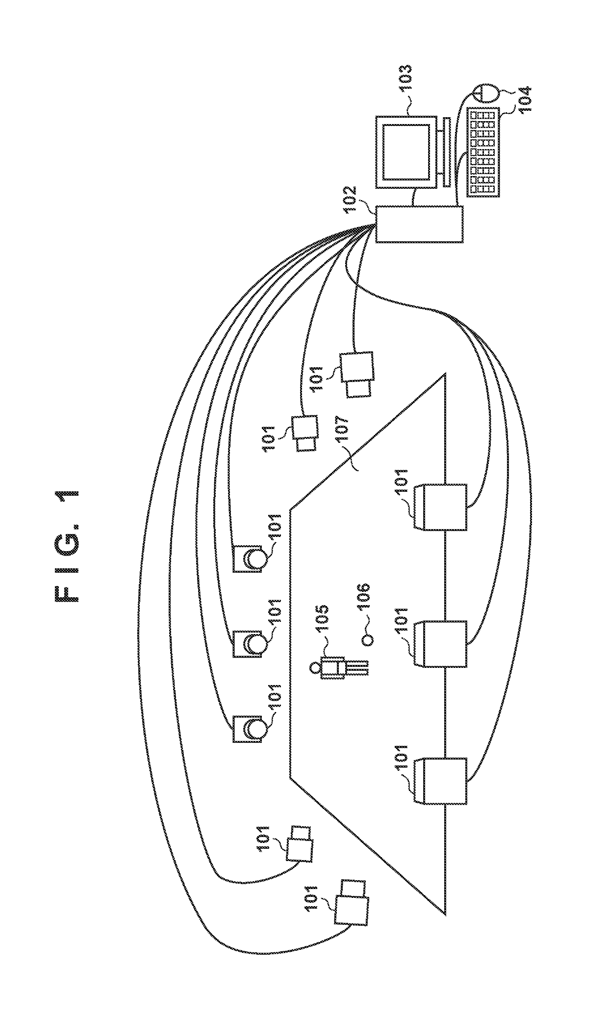
[0027]FIG. 1 illustrates a capturing environment and configuration of an image processing system in an embodiment. As in the figure, the present system is configured by a plurality of cameras 101; an information processing apparatus 102 that receives and accumulates the images captured by each of the cameras 101, and generates virtual-viewpoint images; a monitor 103; a user instruction input unit 104 such as a keyboard or a mouse; and the like. Also, in the embodiment, as shown graphically, an example in which objects 105 and 106 are positioned on a floor 107 which is a background image is illustrated. Note that in the FIG. 10 cameras are illustrated, but there is no particular limitation to this number. However, it is desirable that there are at least a plurality of cameras on each of the four sides. Also, in the figure, it is envisioned that the object 1...


PUM


Abstract

The invention comprises a depth-image generator which, based on shape information representing a shape of an object in the captured images of the cameras, generates depth images corresponding to the captured images obtained from a plurality of cameras; a detector which, based on a generated depth image, detects a boundary region of the object in a corresponding captured image; a pixel map generator which, based on the boundary region in the captured image detected by the detector, generates a pixel map representing a contributing ratio for generating the virtual-viewpoint image for each pixel position of the captured image; and an output-image generator which generates the virtual-viewpoint image based on the captured images obtained from the plurality of cameras, and the pixel map corresponding to the captured images.

Description

BACKGROUND OF THE INVENTION[0001]Field of the Invention[0002]The present invention is related to a technique for, based on images that are captured from a plurality of viewpoint positions, generating an image from a set virtual-viewpoint position.[0003]Description of the Related Art[0004]A technique of obtaining a three-dimensional model of an object (for example, a person or the like) from images captured by a plurality of cameras, and generating, from a plurality of captured images, an image (hereinafter referred to as a virtual-viewpoint image) at an arbitrary viewpoint (hereinafter referred to as a virtual-viewpoint) at which no camera is actually present is known (for example, Japanese Patent No. 5011224).[0005]At this time, the shape of the object in the virtual-viewpoint image is obtained from the three-dimensional model, and a region that its shape encompasses is generated by texture mapping. The color of a pixel used in this texture mapping is obtained by referencing a real...

Claims


Application Information

Patent Timeline
Patent Type & Authority Patents(United States)
IPC IPC(8): G06T7/55G06T7/13G06T15/20
CPCG06T15/205G06T7/55G06T7/13G06T2200/08G06T2207/10004G06T2207/10028
Inventor HIGUCHI, SHUGOKOIZUMI, TATSURO
Owner CANON KK
Why Eureka
Try Eureka