
Hybrid sealing tool having multiple seal patterns

a hybrid sealing and pattern technology, applied in the field of sealing technology, can solve the problems of causing leakage points at the transition between different thicknesses, difficulty in sealing across multiple variations of layers, and notoriously difficult bag types to achieve sealing, so as to achieve reliable and attractive effect, not cause excessive power draw

Active Publication Date: 2019-11-26
SONICS & MATERIALS
View PDF16 Cites 2 Cited by
  • Summary
  • Abstract
  • Description
  • Claims
  • Application Information

AI Technical Summary

Benefits of technology

The present invention provides a bag with reliable and attractive side seals that do not over-crush the zipper or scar the plastic film. Additionally, the bag design helps prevent excessive power draw due to melting excessive plastic in the vicinity of the zipper.

Problems solved by technology

However, this type of bag is notoriously difficult to seal.
One difficulty lies in sealing across the multiple variations of layers that are unavoidable in creating a gusset.
While these folds are important to form the gussets, they create leak points at the transitions between the different areas of thickness.
While creating a hermetic seal is unreliable with heat, the strength of the seal is good due to its wide width.
One problem with the contoured / bowed anvil approach, however, is that the taper must be gradual and the location of the gussets and fins drifts from bag to bag in production.
Since the tools are contoured away from one another at this point, a leak in this location is almost certain.
A hermetic seal could be created with ultrasonics using a traditional single seal bead, but it resulted in a fragile bond that was unable to withstand real-world abuse.
When the seal experienced flexing or bulging from the internal product or a vacuum burst test, the transition point where four layers meets two layers would become highly stressed and the seal would quickly fail.
Quite often, the film would burst at this transition point, tearing through all layers instead of just creating a small leak path.
This transition point failure had been an insurmountable hurdle for ultrasonic sealing of gussets.
While the system and method of U.S. Pat. No. 10,046,874 provides greatly improved cross seals, as compared to previously known systems and methods, issues remain with respect to the manufacture of gusseted and zippered bags in some situations.
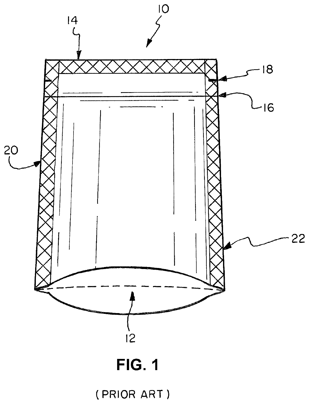
The current standard for standup pouches uses premade pouches requiring a middleman (called a converter) that makes the empty pouches on relatively expensive equipment that takes up a significant amount of floor space.
The pouches are then shipped to the packer where the product is inserted, and the pouch is sealed on the top thereof using an entirely different (also relatively expensive) machine.
The pouches made using this method are generally attractive and have effective seals but are costly due to the extra steps required.
The problem is that the side seals on pouches made on vertical machines have heretofore been generally unreliable and unattractive.
However, it has also been found that that same system and method may not provide optimum results on the zipper end (top) of the pouch when used to try to create the side seals.
Specifically, the thickness of the zipper may cause a high power draw due to melting excessive plastic on the top of the pouch.
Further the system and method disclosed in U.S. Pat. No. 10,046,874 has a tendency to over-crush the zipper and scar the plastic film.

Method used


Image

  • Hybrid sealing tool having multiple seal patterns
  • Hybrid sealing tool having multiple seal patterns
  • Hybrid sealing tool having multiple seal patterns

Examples


Embodiment Construction

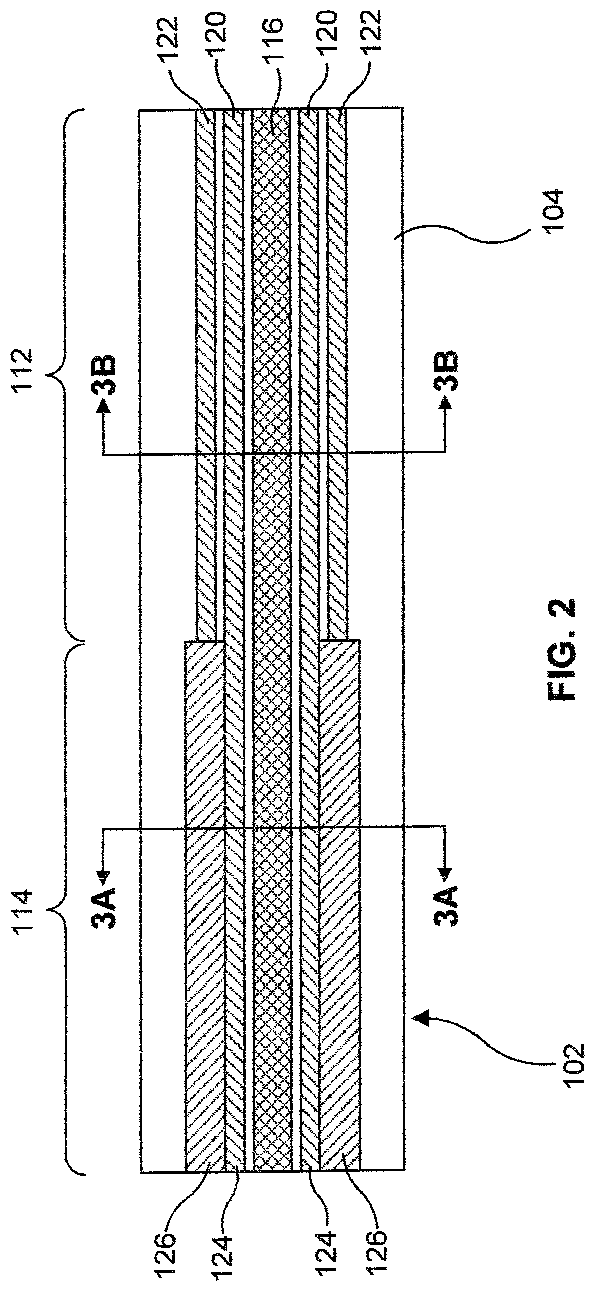
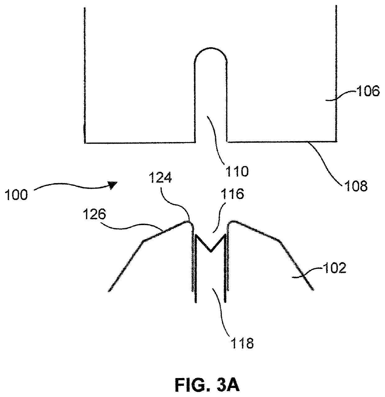
[0031]FIGS. 2-3B illustrate a sealing tool (100) for sealing a work piece, such as the gusseted and zippered bag, according to an exemplary embodiment of the present invention. As is typical, the tool (100) includes a horn or sonotrode and an anvil. As one skilled in the art will understand, the tool (100) is mounted in an ultrasonic welding machine and the horn (or anvil, or both the horn and the anvil) is actuated with high-frequency mechanical vibrations generated by a converter connected thereto that converts electrical impulses from a power supply into the mechanical vibrations at ultrasonic frequencies (e.g., 14 kHz or more). See, for example, U.S. Pat. No. 8,950,458, incorporated herein by reference.

[0032]During use, a portion of a work piece to be sealed, such as a bag, is received between opposing surfaces of the horn and the anvil, and the gap between the surfaces is closed or reduced to sandwich the bag by displacing (e.g., manually or automatically) one or both of the ho...


PUM

PropertyMeasurementUnit
heightaaaaaaaaaa
heightaaaaaaaaaa
heightaaaaaaaaaa

Abstract

A sealing tool includes an anvil and a horn, at least one of which includes a sealing surface having a gusset sealing section and a zipper sealing section, each configured differently than the other. The gusset sealing section includes a plurality of sealing beads including a gusset section barrier sealing bead having a first height and a protective sealing bead having a second height, the second height being smaller than the first height. The zipper sealing section includes a zipper section barrier sealing bead extending and a tapered section adjacent to the zipper section sealing bead, the tapered section tapering from a larger height adjacent to the zipper section sealing bead to a smaller height as a distance away from the zipper section sealing bead increases.

Description

FIELD OF THE INVENTION[0001]The present invention relates generally to sealing technology, and more specifically, relates to gusseted and zippered pouches, and systems and methods for making such gusseted and zippered pouches employing ultrasonic and / or heat sealing technology.BACKGROUND OF THE INVENTION[0002]Gusseted bags have become very popular in the packaging industry. They are used extensively in the packaging of frozen foods as well as for coffee and cereal bags. Gusseted bags allow for expansion and can hold bulkier contents as compared to common pillow bags. However, this type of bag is notoriously difficult to seal. One difficulty lies in sealing across the multiple variations of layers that are unavoidable in creating a gusset.[0003]The ends of a gusseted bag have several areas of folded material which forms the gussets. There may be areas with four layers of material on the outer edges, areas with two layers of material inboard thereof, and another area with four layers ...

Claims


Application Information

Patent Timeline
Patent Type & Authority Patents(United States)
IPC IPC(8): B32B37/00B29C65/00B29C65/08B65B51/22
CPCB29C66/43121B29C66/73921B65B51/225B29C66/1122B29C66/849B29C65/08B29C65/7451B29C66/006B29C66/135B29C66/232B29C66/346B29C66/43B29C66/431B29C66/4312B29C66/81415B29C66/81422B29C66/81427B29C66/81431B29C66/81435B29C66/8322B29C66/83221B29L2005/00B29L2031/7128B65B51/146B65D33/2508
Inventor AURAND, WILLIAM G.
Owner SONICS & MATERIALS
Learn More