
Method for controlling a processor of an electronic enclosure mounted on a wheel of a motor vehicle

a technology of electronic enclosure and processor, which is applied in the direction of vehicle registration/indicating, instruments, and registering/indicating, etc., can solve the problems of high energy consumption, inability to detect a large number, and high cost of the calculation time of the processor, so as to achieve low energy consumption, high frequency, and rapid initialization.

Active Publication Date: 2019-12-10
CONTINENTAL AUTOMOTIVE FRANCE +1
View PDF53 Cites 0 Cited by
  • Summary
  • Abstract
  • Description
  • Claims
  • Application Information

AI Technical Summary

Benefits of technology

The patent describes a technology that reduces energy consumption and improves efficiency in a contact detecting device. It uses a standby mode and a transmission mode that is only triggered after a significant change in a contact's data is detected. This condition helps prevent unnecessary movement of vehicles caused by traffic issues. The technology also includes an initialization procedure for the digital filter, which ensures consistent and accurate data detection. Additionally, it includes a mechanism to prevent infinite loop operations due to malfunctions. Finally, it allows for the detection of significant changes in the contact data during transmission mode, which then prompts interruption of the transmission mode to reinitialize the digital filter for further use.

Problems solved by technology

However, the calculation of the values of these characteristic data of the contact patch of the tire, carried out by the processor integrated into each electronic module, has proved to be costly in terms of the calculation time of said processor, and therefore highly energy-intensive.
This restriction imposed for reasons of energy saving means that it is impossible to detect a large number of situations in which a knowledge of the variation of characteristic data of the contact patch of tires could provide useful information for the operation of the central unit and the control of the parameters processed by this unit.

Method used


Image

  • Method for controlling a processor of an electronic enclosure mounted on a wheel of a motor vehicle
  • Method for controlling a processor of an electronic enclosure mounted on a wheel of a motor vehicle

Examples


Embodiment Construction

[0066]The method according to the invention is intended to provide a function of controlling a processor of an electronic enclosure mounted on a wheel, fitted with a tire, of a motor vehicle, for the purpose of calculating characteristic data of the contact patch of said tire on the ground, and transmitting these data toward a central unit integrated into said motor vehicle.

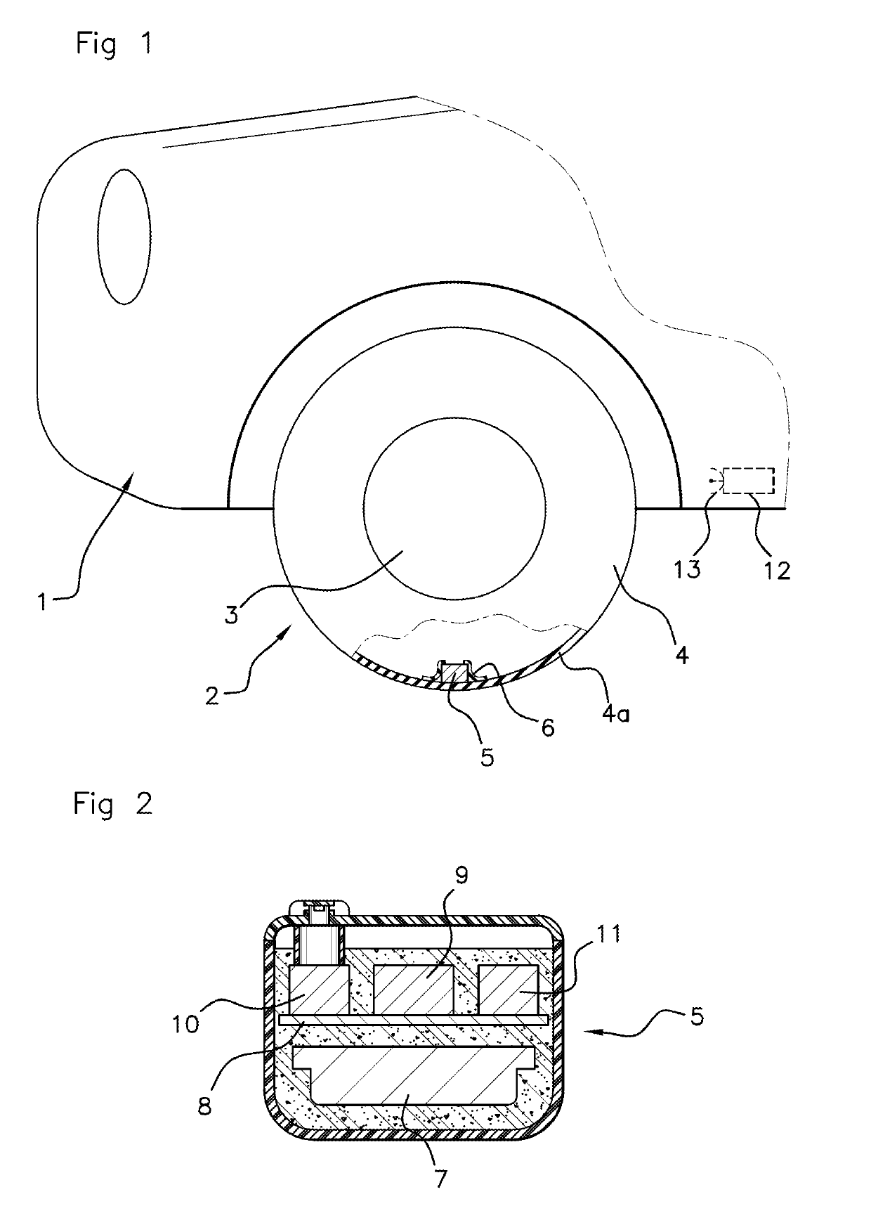
[0067]For the execution of this method, as shown in FIG. 1, the vehicle 1 comprises wheels such as the wheel 2, composed in a conventional way of a rim 3 fitted with a tire 4, and a monitoring system for monitoring parameters such as the pressure and temperature of each of said tires and the radial acceleration of said wheel, comprising, firstly, an electronic enclosure 5 associated with each wheel 2.

[0068]According to the example shown in FIGS. 1 and 2, this electronic enclosure 5 is positioned on the inner face of the tread 4a of the tire 4. In order to secure the enclosure, it is inserted into a flexible recep...


PUM


Abstract

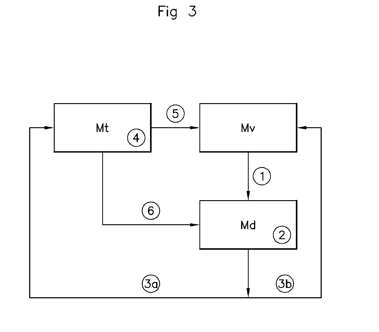
In a method for controlling a processor on a wheel, wheel operation parameters are calculated and transmitted to a CPU. A first default operating mode (standby mode) is defined, during which activities related to calculating and checking the characteristic data of the tread mark of the tire are deactivated, a second operating mode for detection of significant changes in the value of a characteristic datum of the tread mark, sought during the appearance, in standby mode, of at least one event likely to be preceded by a significant change in the value, and a third operating mode for calculation and transmission, to a CPU, a sequence of values representing the characteristic datum of the footprint, sought during the confirmation, in detection mode, of a significant change in the value of the characteristic datum of the tread mark, and at the end of which a switch is made into monitoring mode.

Description

[0001]The invention relates to a method for controlling a processor of an electronic enclosure mounted on a wheel, fitted with a tire, of a motor vehicle, for the purpose of calculating operating parameters of said wheel comprising, notably, one or more pieces of characteristic data of the contact patch of said tire on the ground, and transmitting these data toward a central unit integrated into said motor vehicle.BACKGROUND OF THE INVENTION[0002]Increasing numbers of motor vehicles are provided, for safety purposes, with detection systems including electronic enclosures mounted on each of the wheels of the vehicle, enclosing sensors used for measuring parameters such as the radial acceleration of the wheel and the pressure and temperature of the tires fitted to these wheels.[0003]In addition to the measurement of the usual parameters intended to provide the driver with direct information on operating parameters of the wheels, it has also been considered useful to provide additional...

Claims


Application Information

Patent Timeline
Patent Type & Authority Patents(United States)
IPC IPC(8): B60C23/00B60C23/06G07C5/08B60C23/04B60C19/00
CPCB60C23/0488B60C23/0459B60C23/0454B60C23/064G07C5/085B60C23/0474B60C2019/004
Inventor GUINART, NICOLASFUDULEA, OLIVIERBOISSET, JEAN-PHILIPPE
Owner CONTINENTAL AUTOMOTIVE FRANCE
Learn More