
Apparatus and method for testing compressed gas dispensing stations

a gas dispensing station and apparatus technology, applied in the direction of fluid pressure measurement by thermal means, container discharging methods, instruments, etc., can solve the problems of large number of vehicles not available, and the conditions desired for testing may not be practical

Active Publication Date: 2019-12-10
AIR PROD & CHEM INC
View PDF11 Cites 8 Cited by
  • Summary
  • Abstract
  • Description
  • Claims
  • Application Information

AI Technical Summary

Benefits of technology

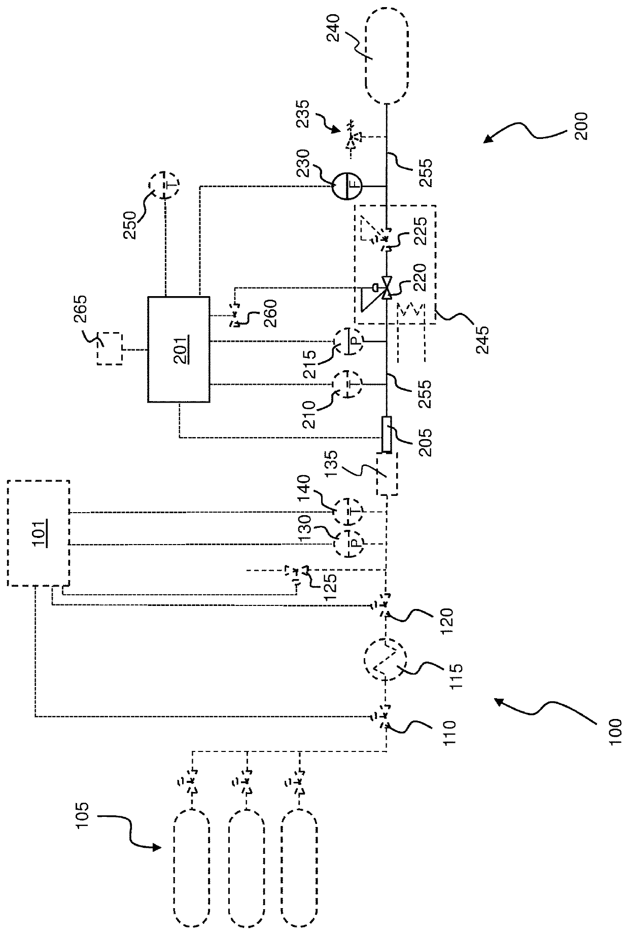
The present patent relates to a testing apparatus and method for compressed gas dispensing stations. The testing apparatus includes a receptacle for connecting to a dispensing nozzle of the station, a fluid transfer line with a back pressure regulator, a mass flow sensor, and a controller. The method involves measuring the mass of gas transferred through the fluid transfer line and calculating the representative fill pressure based on the mass measurement. The controller adjusts the pressure setting of the back pressure regulator accordingly. The testing apparatus and method can be used to ensure the accuracy and reliability of compressed gas dispensing stations.

Problems solved by technology

Some conditions desired for testing may not be practical at the present time.
For example, industry may desire to test a hydrogen or CNG dispensing station for conditions where hydrogen or CNG is dispensed to multiple vehicles in rapid succession, but a large number of vehicles are not available.

Method used


Image

  • Apparatus and method for testing compressed gas dispensing stations

Examples


Embodiment Construction

[0048]The ensuing detailed description provides preferred exemplary embodiments only, and is not intended to limit the scope, applicability, or configuration of the invention. Rather, the ensuing detailed description of the preferred exemplary embodiments will provide those skilled in the art with an enabling description for implementing the preferred exemplary embodiments of the invention, it being understood that various changes may be made in the function and arrangement of elements without departing from the scope of the invention as defined by the claims.

[0049]The articles “a” and “an” as used herein mean one or more when applied to any feature in embodiments of the present invention described in the specification and claims. The use of “a” and “an” does not limit the meaning to a single feature unless such a limit is specifically stated. The article “the” preceding singular or plural nouns or noun phrases denotes a particular specified feature or particular specified features ...


PUM

PropertyMeasurementUnit
temperatureaaaaaaaaaa
pressureaaaaaaaaaa
fill pressureaaaaaaaaaa

Abstract

Testing apparatus and method for testing compressed gas dispensing stations where a back pressure regulator is used to imitate filling of receiving vessels without the need for receiving vessels. A mass flow sensor measures the mass of compressed gas dispensed to the testing apparatus, and a controller calculates the pressure for the back pressure regulator to imitate filling of a receiving vessel.

Description

BACKGROUND[0001]Compressed gas dispensing stations are being developed to fill hydrogen-powered vehicles, and compressed natural gas-powered vehicles. Designs of compressed gas dispensing stations can vary from manufacturer to manufacturer.[0002]Industry desires to test hydrogen dispensing stations and compressed natural gas (CNG) dispsensing stations.[0003]Industry desires to test compressed gas dispensing stations under varying conditions. Some conditions desired for testing may not be practical at the present time. For example, industry may desire to test a hydrogen or CNG dispensing station for conditions where hydrogen or CNG is dispensed to multiple vehicles in rapid succession, but a large number of vehicles are not available. Industry may desire to test a hydrogen or CNG dispensing station for various prescribed initial pressures in the receiving vessel, where receiving vessels with the prescribed initial pressures are not available. Industry may desire to test a hydrogen or...

Claims


Application Information

Patent Timeline
Patent Type & Authority Patents(United States)
IPC IPC(8): G01L11/00B65D83/14
CPCG01L11/002B65D83/14F17C5/06F17C13/025F17C13/026G01F1/00G01K13/00G01L11/00F17C2201/0109F17C2221/012F17C2221/033F17C2223/0123F17C2223/035F17C2223/036F17C2225/0123F17C2225/035F17C2225/036F17C2250/0626F17C2250/0631F17C2265/061F17C2265/063F17C2270/0168F17C13/02F17C2205/0332F17C2205/0338F17C2260/026F17C2227/0393F17C2227/0341
Inventor COHEN, JOSEPH PERRY
Owner AIR PROD & CHEM INC
Learn More