
Grinding apparatus

a technology of grinding machine and grinding plate, which is applied in the direction of grinding machine, grinding machine components, manufacturing tools, etc., can solve the problem of reducing the wafer grinding ra

Active Publication Date: 2019-12-17
TOKYO SEIMITSU
View PDF23 Cites 0 Cited by
  • Summary
  • Abstract
  • Description
  • Claims
  • Application Information

AI Technical Summary

Benefits of technology

[0009]According to the structure of the second aspect of the invention, since the control unit corrects the target thickness of the wafer after the fine grinding on the basis of the average thickness across the entire surface of the wafer while taking into consideration whether the thickness of the wafer is thin or thick, excessive or insufficient grinding, which often occurs when the wafer having waviness is ground, can be prevented or reduced.
[0011]According to the third aspect of the invention, since the measuring spots of the thickness measuring means are scanned on the wafer without movement of the thickness measuring means, the thickness measuring means can be installed in a space-saving manner and, at the same time, the thickness across the entire surface of the wafer is measured with the thickness measuring means, so that the wafer can be ground precisely to the target thickness.
[0017]According to the structure of the sixth aspect of the invention, since the thickness measuring means can be installed in the column opposite the transfer means, the thickness measuring means can be easily provided without additional preparation of a jig or the like for placing the thickness measuring means.
[0020]Since the present invention measures the thickness of the wafer while the wafer is being transferred, the present invention measures the thickness across the entire surface of the wafer with the throughput kept, so that the wafer can be precisely ground to the target thickness.

Problems solved by technology

However, in such a grinding apparatus disclosed in Japanese Patent Application No. 2016-16457 as described above, since the measurement of the thickness of the wafer is performed while the rough grinding or fine grinding is being performed, a grinding wheel must be retreated upward, for example, when the thickness at the center of the wafer is measured, and therefore such a problem occurs that the throughput of wafer grinding is reduced.

Method used


Image

  • Grinding apparatus
  • Grinding apparatus
  • Grinding apparatus

Examples


Embodiment Construction

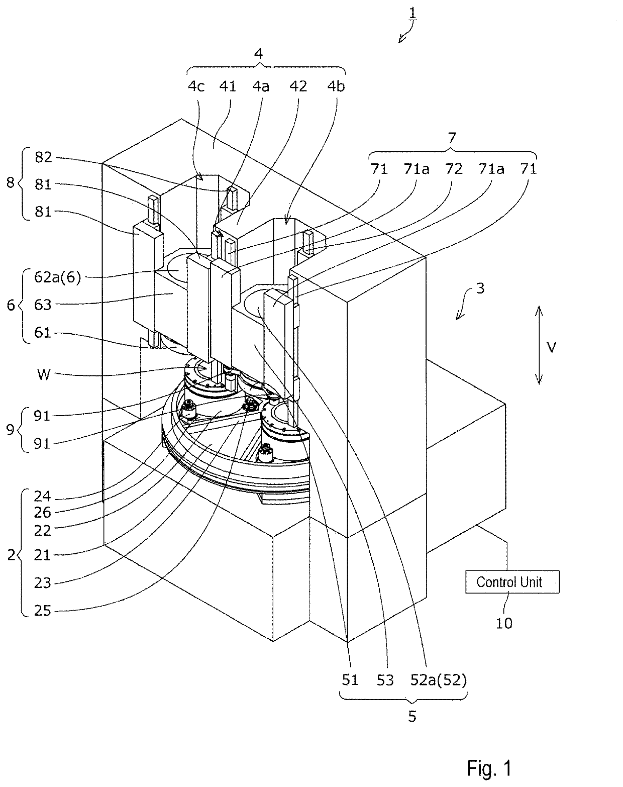
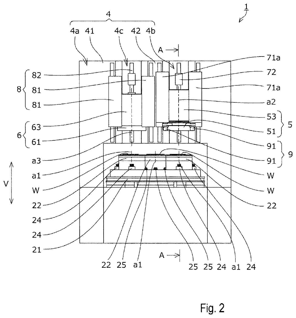
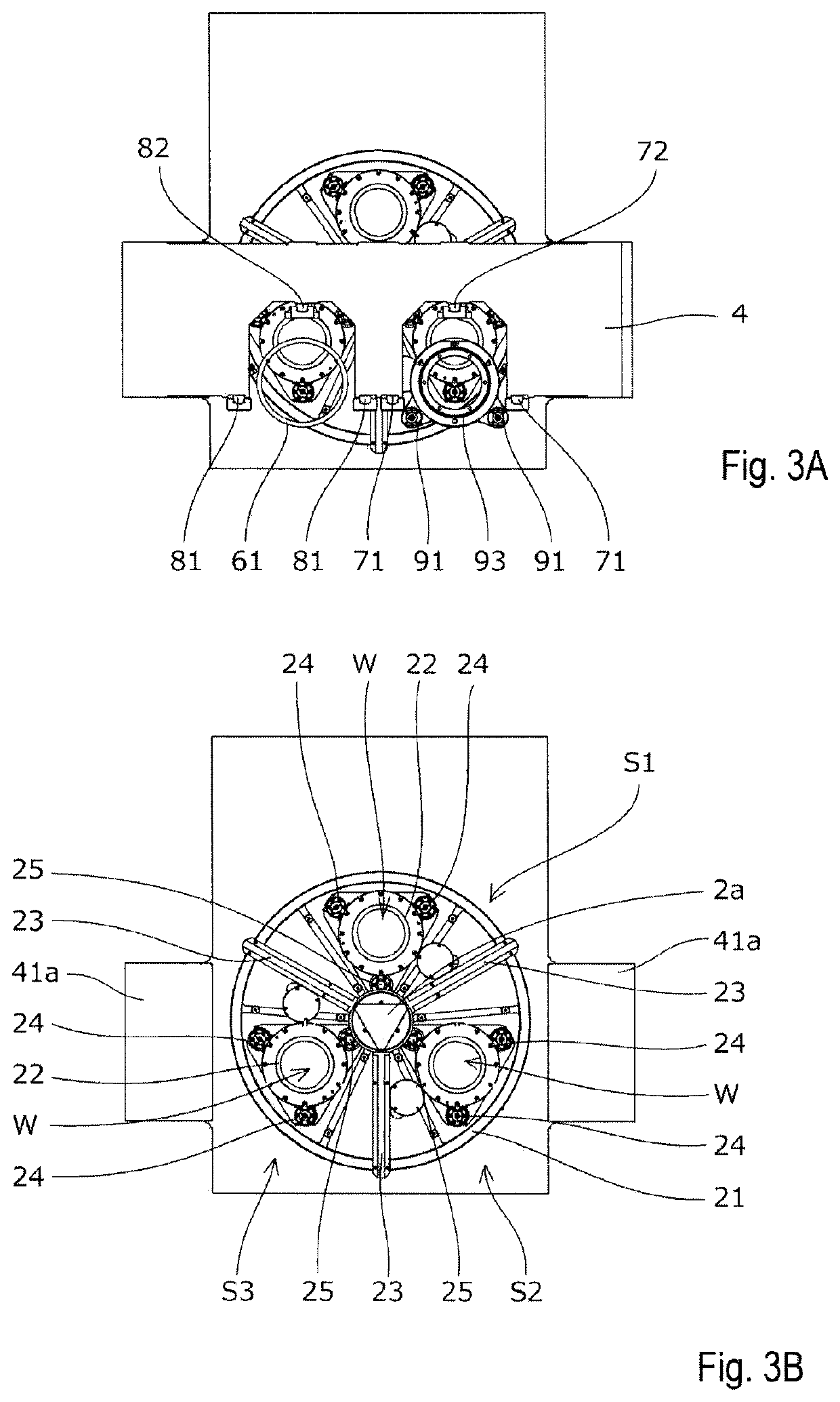
[0030]In order to achieve the object that thickness measurement across an entire surface of a wafer is performed without degradation of the throughput of wafer grinding and the wafer is ground precisely to a target thickness, a grinding apparatus according to the present invention is embodied by a grinding apparatus provided with a rough grinding stage for roughly grinding a wafer, a fine grinding stage for fine grinding the wafer, and a transfer means for transferring the wafer, the grinding apparatus including a thickness measuring means for measuring the thickness of the wafer while the wafer is being transferred, and a control means for computing the thickness of the wafer before fine grinding on the basis of measured values of the thickness measuring means and correcting a target thickness after the fine grinding.

[0031]Herein below, a grinding apparatus 1 according to an embodiment of the present invention is described with reference to the drawings. It should be noted that, wh...


PUM


Abstract

A grinding apparatus that performs thickness measurement across an entire wafer surface without degradation of throughput of wafer grinding and grinds the wafer precisely to a target thickness. A grinding apparatus includes a rough grinding stage for roughly grinding a wafer and a fine grinding stage for finely grinding the wafer. A first thickness measuring means for measuring the thickness of the wafer while the wafer is being transferred is provided to a column so disposed as to span an index table. A control unit of the grinding apparatus corrects a target thickness after fine grinding and computes a target thickness after correction on the basis of an average thickness across the entire surface of the wafer before fine grinding obtained from measured values of the first thickness measuring means.

Description

BACKGROUND OF THE INVENTION1. Field of the Invention[0001]The present invention relates to a grinding apparatus for grinding the back side of a wafer.2. Description of the Related Art[0002]In the field of semiconductor manufacturing, back grinding for grinding the back side of a wafer is performed in order to thin a semiconductor wafer, such as a silicon wafer (referred to below as “wafer”). As a grinding apparatus for performing such back grinding, one that roughly grinds a wafer thicker than a target thickness and thereafter finely grinds the roughly-ground wafer to the target thickness is known.[0003]In Japanese Patent Application No. 2016-16457, a grinding apparatus that measures the thickness of a wafer with a contact-type thickness measuring means during the rough grinding or fine grinding is disclosed. The positions of measurement where the thickness measuring means measures the thickness of the wafer are arranged on a plurality of concentric circles centered at the center of...

Claims


Application Information

Patent Timeline
Patent Type & Authority Patents(United States)
IPC IPC(8): B24B7/22B24B51/00B24B49/12
CPCB24B7/228B24B51/00B24B49/12B24B27/0023B24B27/0069B24B49/04
Inventor KANAZAWA, MASAKISHIMODA, MAKOTO
Owner TOKYO SEIMITSU
Learn More