

Steering wheel
a steering wheel and steering wheel technology, applied in the field of steering wheels, can solve the problems of deterioration of the steering wheel tactile impression, and achieve the effect of smooth disposal
- Summary
- Abstract
- Description
- Claims
- Application Information
AI Technical Summary
Benefits of technology
Problems solved by technology
Method used
Image

Examples
Embodiment Construction
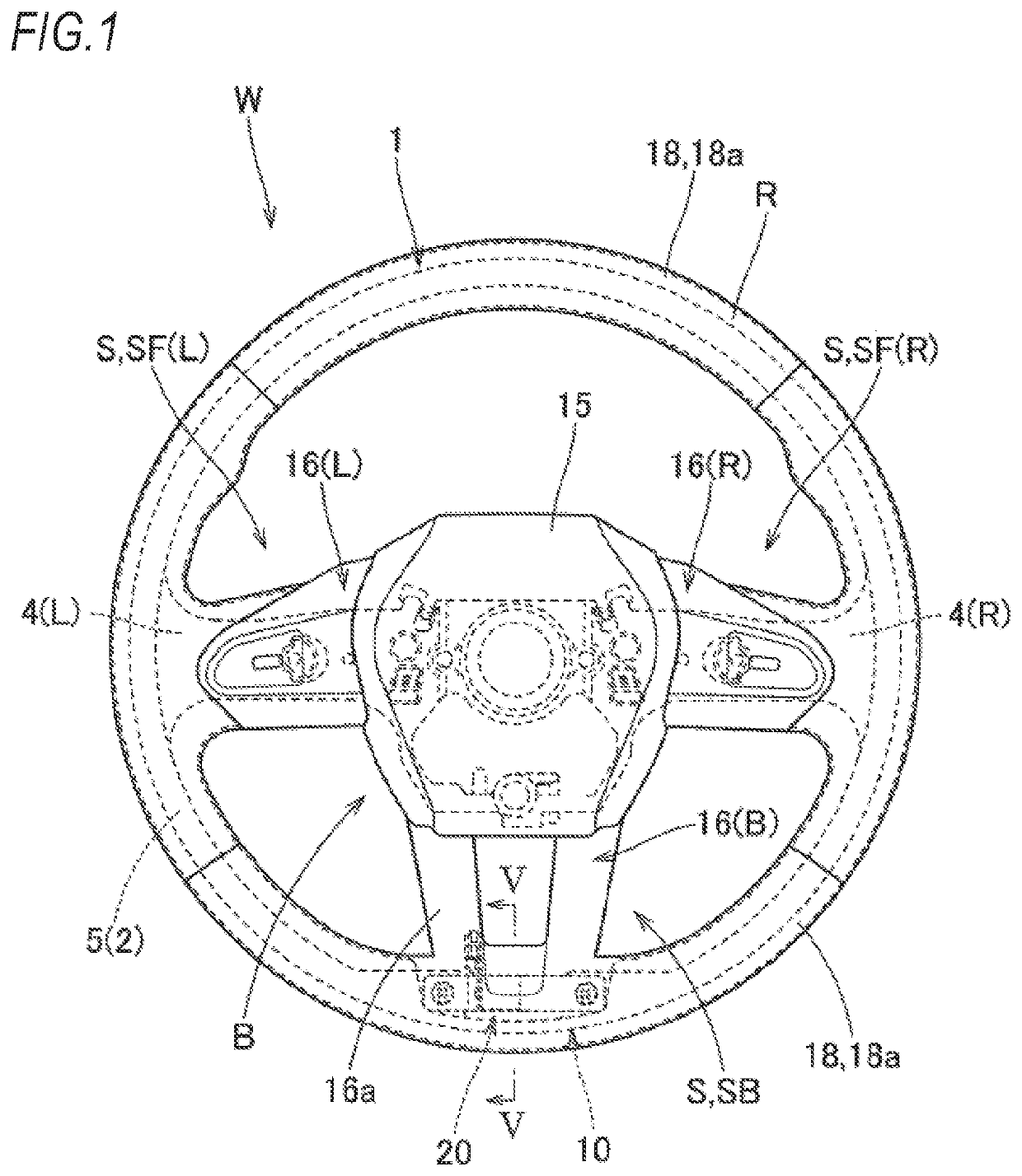
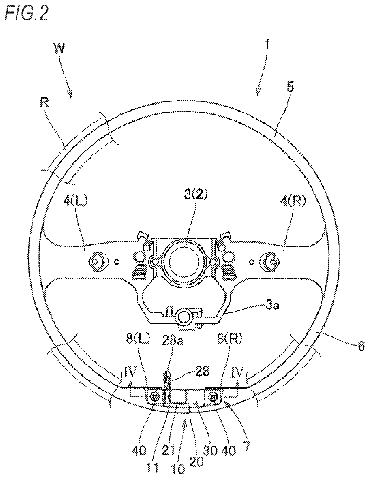
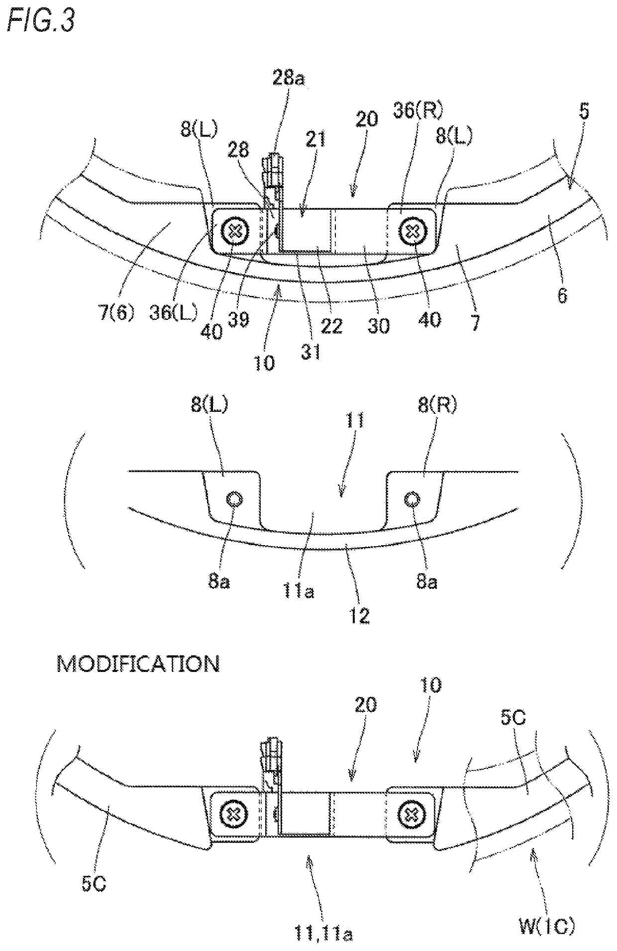
[0030]Hereinafter, an embodiment of the present invention will be described with reference to the drawings. As shown in FIGS. 1 and 2, a steering wheel W of the embodiment includes a vibration device 20 and a steering wheel main body 1. The steering wheel main body 1 includes a substantially annular ring portion R gripped by a driver at the time of steering, a boss portion B disposed at the center of the ring portion R and fastened to a steering shaft (not shown), and a plurality of (three in the present embodiment) spoke portions S connecting the ring portion R and the boss portion B. Further, the steering wheel main body 1 includes a core member 2 disposed so as to connect the ring portion R, the boss portion B, and the spoke portions S. The core member 2 includes a boss core member 3 disposed in the boss portion B, a spoke core member 4 disposed in the spoke portions 5, and a ring core member 5 disposed in the ring portion R. Further, in the core member 2, a portion to be connect...
PUM
 Abstract
Description
Claims
Application Information