Device for producing water droplets for air humidification and a humidification system with such devices

a technology of air humidification and water droplets, which is applied in air humidification systems, lighting and heating apparatuses, heating types, etc., can solve the problems that the concept has not been used in practical installations fit for everyday use, and achieve the effect of cost and energy saving

Active Publication Date: 2019-12-17
CONDAIR GRP
View PDF17 Cites 3 Cited by
  • Summary
  • Abstract
  • Description
  • Claims
  • Application Information

AI Technical Summary

Benefits of technology

[0004]The problem to be solved by the present invention is therefore to provide an improved humidifier and in particular to provide a cost and energy efficient and hygienically nonhazardous humidification of rooms or other compartments with very small droplets of water which is adapted for permanent installation in cabinets, such as rooms and other compartments, and which is suitable for every-day use with a long life-cycle of the installation.
[0007]It has been found that such a device with the mesh droplet generator in combination with the through duct with inlet and outlet to the reservoir and with the controlled valve arrangement results in a device that can securely avoid the leaking of water when such devices are installed on a wall or roof of a compartment, in particular a room, and can securely avoid residual water in an amount that may pose hygienic problems. When used in the system for humidification or adiabatic cooling of several compartments, such as rooms or cabinets or terrariums, comprising a closed ring water conduit leading to the several compartments, such devices allow the controlled, safe humidification of the compartments. The devices are connected in series into the water line and are arranged to release droplets into the respective compartment. At least one humidification sensor and in particular one humidification sensor per compartment, allows the control of one or several devices.
[0008]In a preferred embodiment the reservoir is provided with a pressure equalizing opening at a point away from the mesh and above the fill-level of the reservoir. Such an opening allows to passively avoid an overpressure on the mesh and thus performs this function very securely and independently of the valve control. A mesh overpressure might lead to water dropping out of the mesh by drops so large that they may be visually detected as such or may be harmful to furniture or goods in the compartment. As well the mesh itself may be harmed by overpressure and its lifetime may be reduced. The device and system is improved in this respect by the preferred embodiment.
[0009]In a further preferred embodiment the device allows to flush the water lines and comprises to this end a throttle within the duct and the valve arrangement is provided with a first line connecting with the duct at an upstream point of the duct ahead of the throttle and a second line connecting with the duct at a downstream point of the duct after the throttle, and with a third line leading to the reservoir, the valve arrangement being controllable by the control unit to connect in one position of the valve arrangement the first line and the second line within the valve arrangement while the third line is disconnected from the first and second line and to connect in a second position of the valve arrangement the third line with the duct. Flushing of water lines of the valve arrangement assures that no hygienic hazards may be posed by the device and system at all time.
[0011]To avoid any chance of contamination of the water in the reservoir for the embodiment with an overpressure opening, such opening is provided with an air-permeable particle-tight closure, in particular a hydrophobic membrane. In a further preferred embodiment the water line providing water from the valve arrangement to the reservoir opens to the reservoir at a position that allows the mesh to be flushed by the water entering the reservoir. This allows to remove air bubbles that may be present on the mesh this flushing water stream when the reservoir is filled.

Problems solved by technology

However, this concept has so far not been used in practical installations fit for every-day use.

Method used


Image

  • Device for producing water droplets for air humidification and a humidification system with such devices
  • Device for producing water droplets for air humidification and a humidification system with such devices

Examples


Embodiment Construction

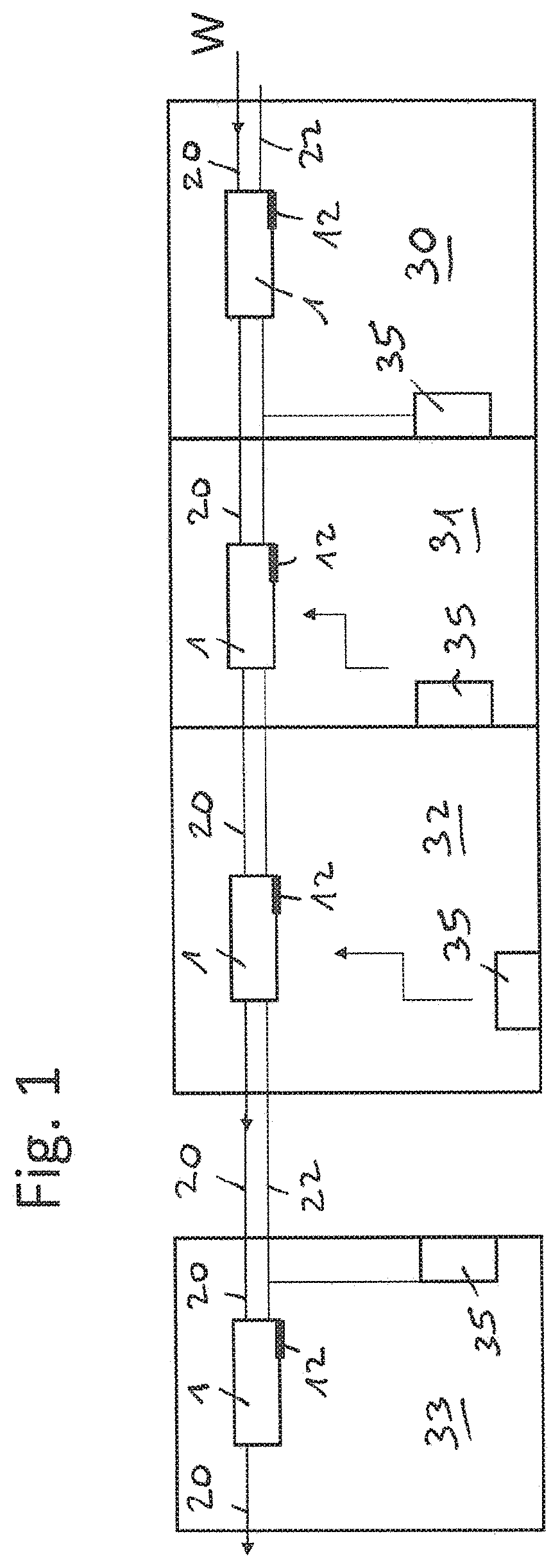
[0018]FIG. 1 shows four compartments. Such compartments may be rooms of a building, such as office rooms or living rooms. The compartments may as well be display cabinets for food, terrariums, refrigerators or any other compartments that shall be humidified and / or cooled by adiabatic cooling which can be effected with a very fine mist of water droplets or in other words nebulized or atomized water as well.

[0019]The number of compartments, for example rooms is of course not limited. Only one compartment may be humidified as explained below or a very large number of compartments. Doors and windows and other features of the compartments are not shown for the sake of simplicity of the drawings. A water conduit 20 is shown that comes from a water source and leads to all rooms that shall be humidified. The water can be tap water or can preferably be demineralized water that may have been additionally treated by ozonisation or with UV light and / or may have been treated with silver ions. Th...


PUM

PropertyMeasurementUnit
shapeaaaaaaaaaa
pressureaaaaaaaaaa
hydrophobicaaaaaaaaaa

Abstract

A humidification device (1) is shown wherein water is nebulized by a vibrating mesh with very small holes. The mesh is part of a reservoir which is fed by a valve arrangement which allows to direct water from a conduit over several water lines within the device either back to the conduit or into the reservoir. The device and a system with such devices allow to humidify and / or cool compartments such as rooms with a very fine mist of water which is hardly visually detectable. The system and device is adapted to be part of a permanent installation with low maintenance.

Description

CROSS REFERENCE TO RELATED APPLICATIONS[0001]This application is a § 371 national stage of PCT International Application No. PCT / CH2015 / 000143, filed Sep. 28, 2015, claiming priority of European Patent Application 14003395.2 filed Oct. 1, 2014, the contents of each of which are incorporated herein by reference in their entireties.TECHNICAL FIELD[0002]The invention relates to a device for producing water droplets, to a method of operating such a device and to a system for the humidification of compartments using such devices.BACKGROUND ART[0003]There are well known devices for air humidification by evaporating water. It has been contemplated as well to use finely atomized water droplets for decentralized air humidification (16. Status-Seminar “Forschen und Bauen im Kontext von Energie und Umwelt”, 2. / 3. September 2010, Ch. Vogel, Dr. A. Grüniger, Dr. B. Wellig, “Ein behagliches Raumklima durch direkte adiabate Raumluftbefeuchtung mit Tropfen (DART)”). However, this concept has so far...

Claims


Application Information

Patent Timeline
Patent Type & Authority Patents(United States)
IPC IPC(8): B01F3/04B01J19/32F24F6/00F24F6/12
CPCF24F6/12B01J19/32B01F3/04021Y02B30/542B01J2219/32286F24F6/00F24F2006/008Y02B30/54Y02B30/70F24F11/0008G01F23/26B01F23/213
Inventor QUADRONI, DARIOSTREIFF, MATTHIASBUCHER, REMO
Owner CONDAIR GRP
Why Eureka
Try Eureka