Firearm trigger mechanism

a trigger mechanism and firearm technology, applied in the field of firearm trigger mechanisms, can solve the problems of inability to provide a “drop-in” solution, require practice in the use of devices, and high manufacturing and installation costs, and achieve the effect of increasing the fire ra

Active Publication Date: 2019-12-24
RARE BREED TRIGGERS LLC
View PDF21 Cites 10 Cited by
  • Summary
  • Abstract
  • Description
  • Claims
  • Application Information

AI Technical Summary

Benefits of technology

[0010]The present invention provides a semiautomatic trigger mechanism for increasing rate of fire that can be retrofitted into popular existing firearm platforms. In particular, this invention provides a trigger mechanism that can be used in AR-pattern firearms with an otherwise standard M16-pattern bolt carrier assembly. The present invention is particularly adaptable for construction as a “drop-in” replacement trigger module that only requires insertion of two assembly pins and the safety selector. In the disclosed embodiments, the normal resetting of the hammer, as the bolt or bolt carrier is cycled, causes the trigger to be forcibly reset by contact between the hammer and a surface of the trigger member. Once reset, movement of the trigger is blocked by a locking bar and cannot be pulled until the bolt has returned to battery, thus preventing “hammer follow” behind the bolt or bolt carrier.

Problems solved by technology

This allows the firearm to be fired only a single time when the trigger is pulled and held, because the user is not typically able to release the trigger rapidly enough so that the sear engages before the bolt or bolt carrier returns to its in-battery position.
The above-described devices either require practice to use reliably, are complex, and / or are expensive to manufacture and install.
This invention, however, does not provide a “drop-in” solution for existing popular firearm platforms, like the AR15, AK47 variants, or the Ruger 10 / 22™.

Method used


Image

  • Firearm trigger mechanism
  • Firearm trigger mechanism
  • Firearm trigger mechanism

Examples


Embodiment Construction

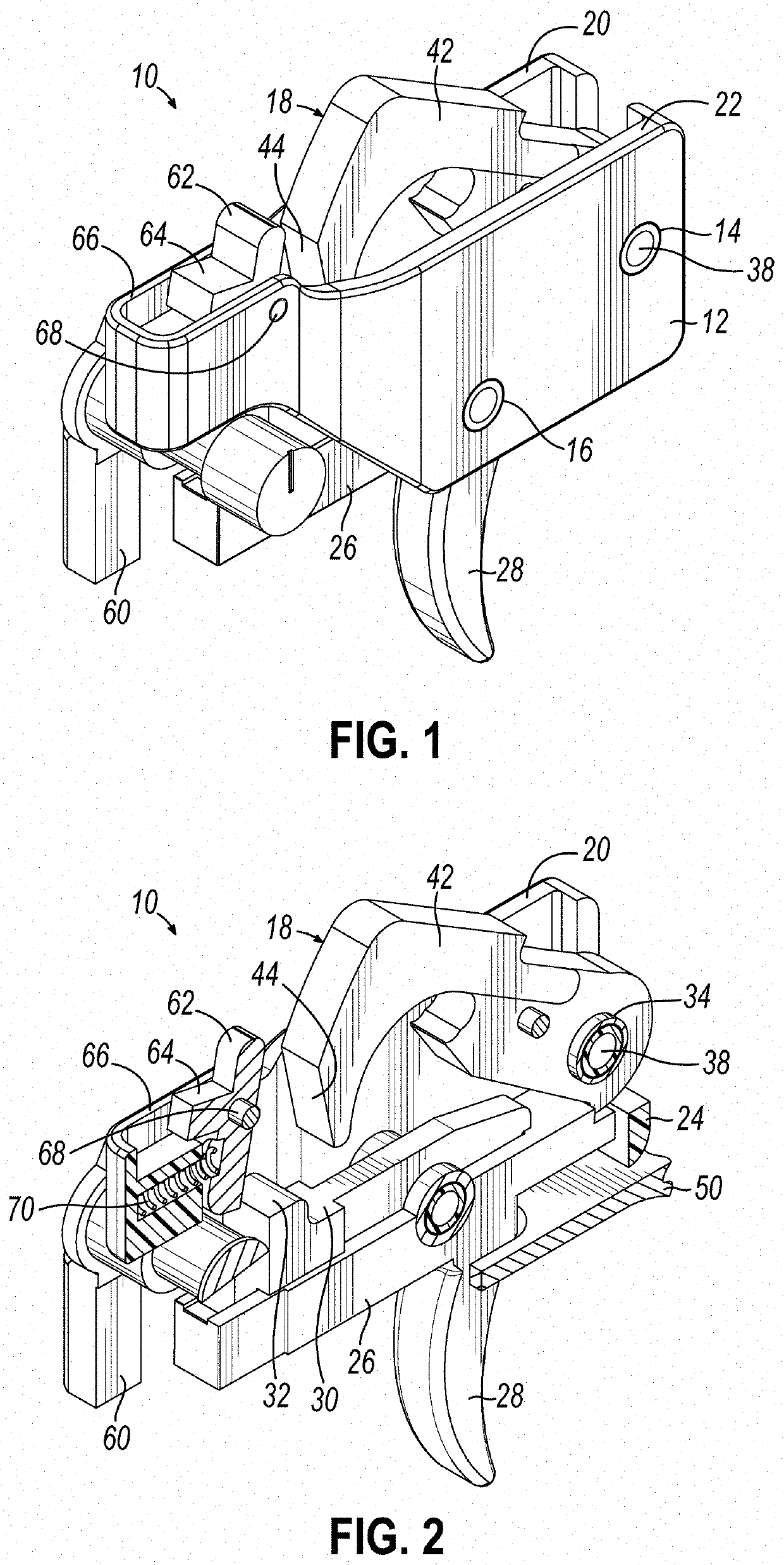
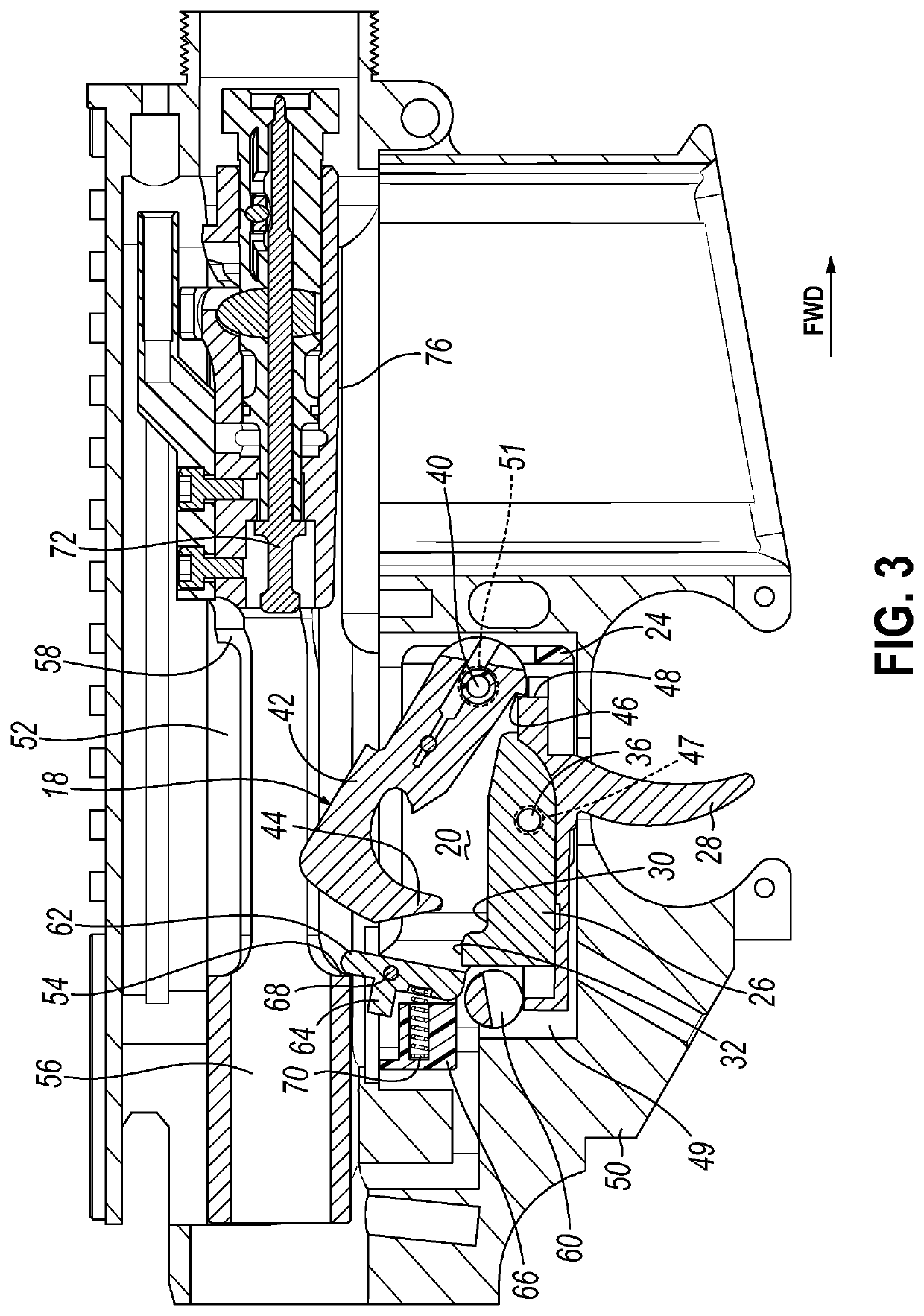
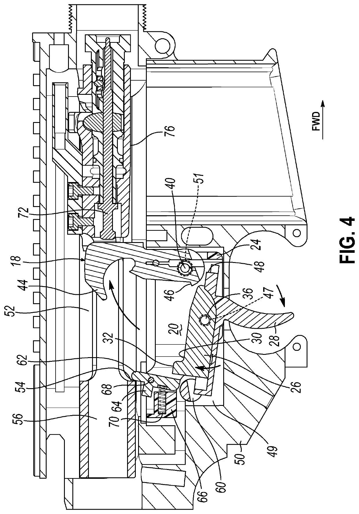
[0018]With reference to the drawing figures, this section describes particular embodiments and their detailed construction and operation. Throughout the specification, reference to “one embodiment,”“an embodiment,” or “some embodiments” means that a particular described feature, structure, or characteristic may be included in at least one embodiment. Thus, appearances of the phrases “in one embodiment,”“in an embodiment,” or “in some embodiments” in various places throughout this specification are not necessarily all referring to the same embodiment. Furthermore, the described features, structures, and characteristics may be combined in any suitable manner in one or more embodiments. In view of the disclosure herein, those skilled in the art will recognize that the various embodiments can be practiced without one or more of the specific details or with other methods, components, materials, or the like. In some instances, well-known structures, materials, or operations are not shown ...


PUM


Abstract

A trigger mechanism for use in a firearm having a receiver with a fire control mechanism pocket, transversely aligned pairs of hammer and trigger pin openings in the pocket, and a bolt carrier that reciprocates and pivotally displaces a hammer when cycled. The trigger mechanism includes a hammer, a trigger member, and a locking bar. The hammer has a sear notch and is mounted in the fire control mechanism pocket to pivot on a transverse hammer pin between set and released positions. The trigger member has a sear and is mounted in the fire control mechanism pocket to pivot on a transverse trigger pin between set and released positions. The trigger member has a surface positioned to be contacted by hammer when the hammer is displaced by cycling of the bolt carrier, the contact causing the trigger member to be forced to the set position. The locking bar is pivotally mounted in a frame and spring biased toward a first position in which it mechanically blocks the trigger member from moving to the release position, and is movable against the spring bias to a second position when contacted by the bolt carrier reaching a substantially in-battery position, allowing the trigger member to be moved by an external force to the released position.

Description

RELATED APPLICATIONS[0001]This application claims priority to U.S. Provisional Patent Application No. 62 / 565,247 filed Sep. 29, 2017, and incorporates the same herein by reference.TECHNICAL FIELD[0002]This invention relates to a firearm trigger mechanism. More particularly, it relates to a semiautomatic trigger that is mechanically reset by movement of the hammer when it is reset by the bolt carrier.BACKGROUND[0003]In a standard semiautomatic firearm, actuation of the trigger releases a sear, allowing a hammer or striker to fire a chambered ammunition cartridge. Part of the ammunitions propellant force is used to cycle the action, extracting and ejecting a spent cartridge and replacing it with a loaded cartridge. The cycle includes longitudinal reciprocation of a bolt and / or carrier, which also resets the hammer or striker.[0004]A standard semiautomatic trigger mechanism includes a disconnector, which holds the hammer or striker in a cocked position until the trigger member is reset...

Claims


Application Information

Patent Timeline
Patent Type & Authority Patents(United States)
IPC IPC(8): F41A19/43F41A19/14F41A19/10F41A19/12F41A17/82
CPCF41A19/43F41A19/12F41A19/10F41A19/14F41A17/82F41A17/46F41A19/15
Inventor ROUNDS, JEFFREY COOPER
Owner RARE BREED TRIGGERS LLC
Why Eureka
Try Eureka