Winding configuration for inductive position encoder

a technology of inductive position encoder and winding configuration, which is applied in the direction of instruments, measurement gauges, measurement devices, etc., can solve the problems of system limitations in the ability to provide certain combinations of features desired by users, relatively robust transducers, and imperfection

Active Publication Date: 2019-12-31
MITUTOYO CORP
View PDF63 Cites 18 Cited by
  • Summary
  • Abstract
  • Description
  • Claims
  • Application Information

AI Technical Summary

Problems solved by technology

Magnetic and inductive transducers are relatively robust to contamination, but not perfectly so.
However, such systems may be limited in their ability to provide certain combinations of features desired by users, such as combinations of compact size, high resolution, cost, robustness to contamination, etc.

Method used


Image

  • Winding configuration for inductive position encoder
  • Winding configuration for inductive position encoder
  • Winding configuration for inductive position encoder

Examples


Embodiment Construction

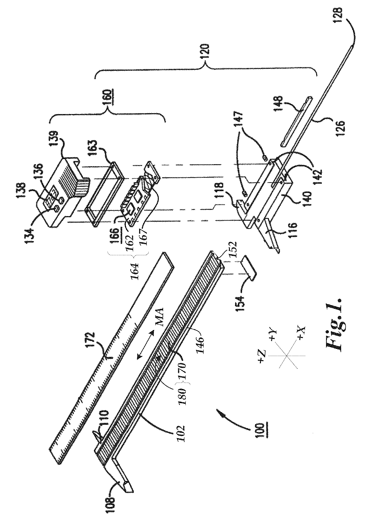
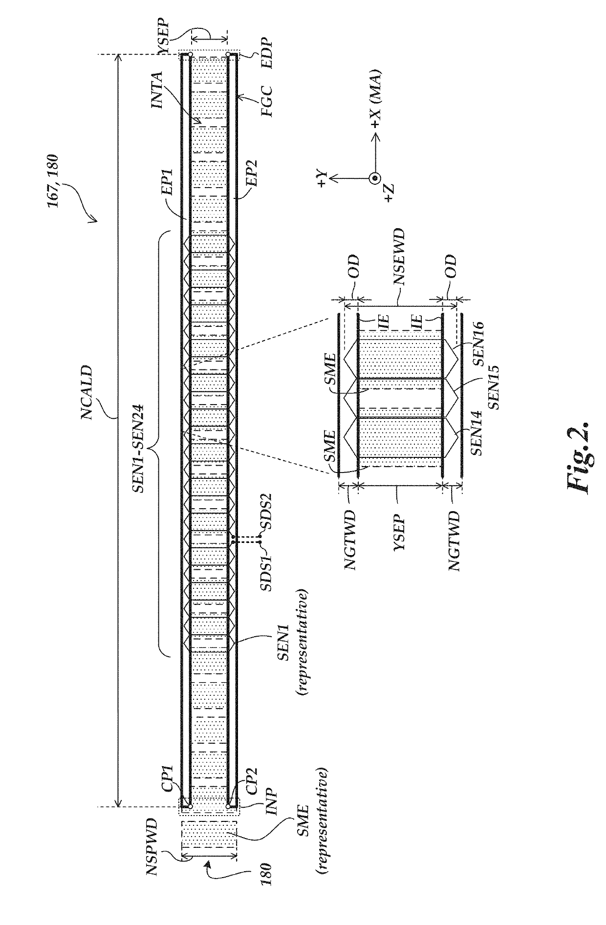
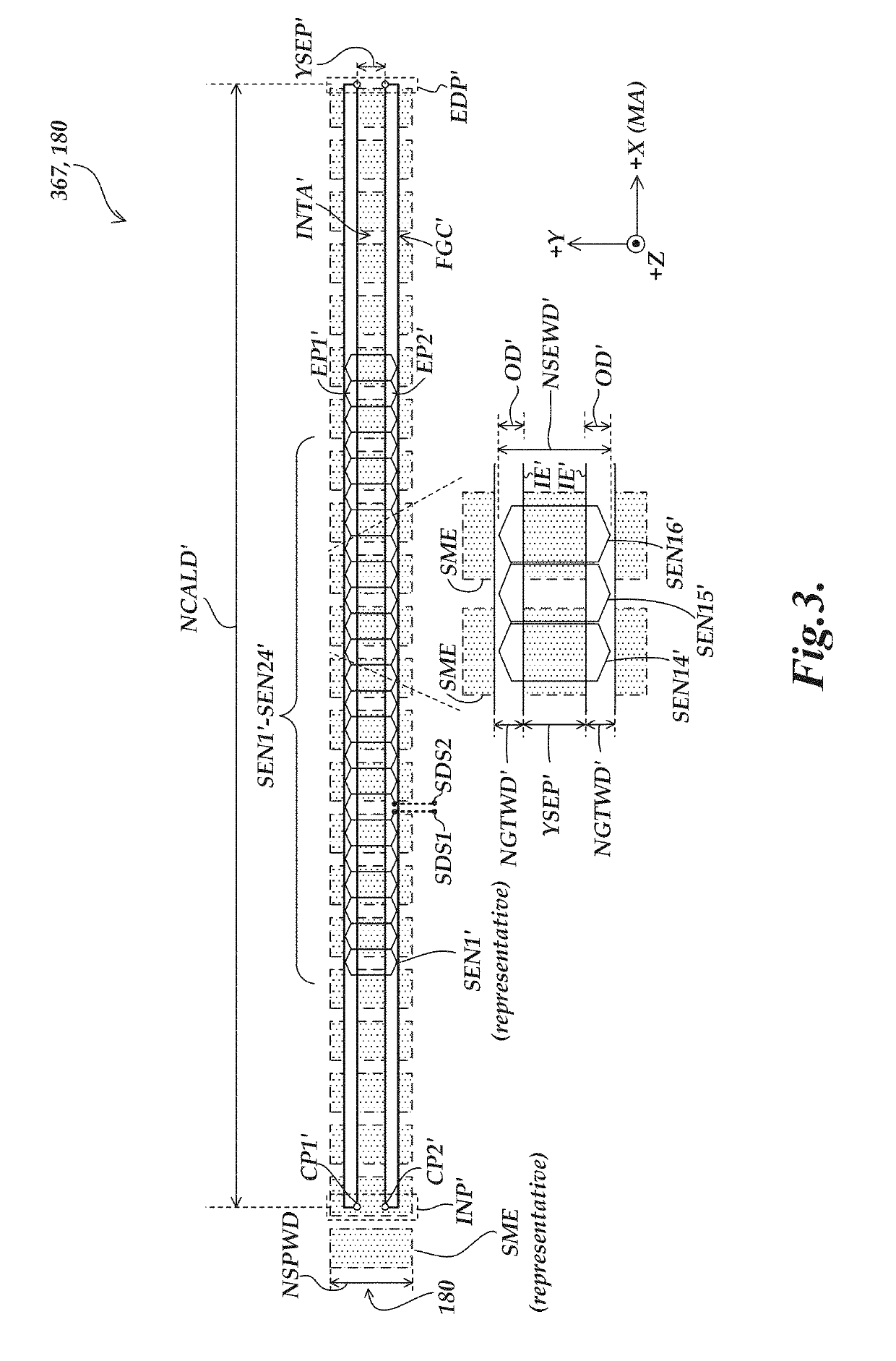
[0015]FIG. 1 is an exploded isometric view diagram of a hand tool type caliper 100 including a scale member 102 having a spar of roughly rectangular cross-section including a scale 170, and slider assembly 120. In various implementations, the scale 170 may extend along the measuring axis direction MA (e.g., corresponding to an x-axis direction) and may include a signal modulating scale pattern 180. A known type of cover layer 172 (e.g., 100 μm thick) may cover the scale 170. Jaws 108 and 110 near a first end of the scale member 102 and movable jaws 116 and 118 on the slider assembly 120 are used to measure dimensions of objects in a known manner. The slider assembly 120 may optionally include a depth bar 126, restrained in a depth bar groove 152 under the scale member 102, by an end stop 154. The depth bar engagement end 128 may extend into a hole to measure its depth. A cover 139 of the slider assembly 120 may include an on / off switch 134, a zero-setting switch 136 and a measuremen...


PUM


Abstract

An electronic position encoder is provided including a scale, a detector and a signal processing configuration. The scale extends along an x-axis direction and includes a signal modulating scale pattern. The detector includes sensing elements and a field generating coil that surrounds an interior coil area. The field generating coil includes first and second elongated portions that each extend along the x-axis direction, connected by an end portion. The elongated portions have a nominal generating trace width dimension along the y-axis direction that is at least 0.1 times the nominal interior coil area width dimension in various embodiments. In various implementations, a conductive shield region of the detector may reduce the effect of a shielded end section of the end portion of the field generating coil on the sensing elements. The shielded end section may be located on a different PCB layer than the elongated portions.

Description

BACKGROUNDTechnical Field[0001]This disclosure relates to measurement instruments, and more particularly to inductive position encoders that may be utilized in precision measurement instruments.Description of the Related Art[0002]Various encoder configurations may include various types of optical, capacitive, magnetic, inductive, movement and / or position transducers. These transducers use various geometric configurations of a transmitter and a receiver in a read head to measure movement between the read head and a scale. Magnetic and inductive transducers are relatively robust to contamination, but not perfectly so.[0003]U.S. Pat. No. 6,011,389 (the '389 patent) describes an induced current position transducer usable in high accuracy applications, U.S. Pat. No. 5,973,494 (the '494 patent) and U.S. Pat. No. 6,002,250 (the '250 patent) describe incremental position inductive calipers and linear scales, including signal generating and processing circuits, and U.S. Pat. No. 5,886,519 (t...

Claims


Application Information

Patent Timeline
Patent Type & Authority Patents(United States)
IPC IPC(8): G01D5/20G01B3/20
CPCG01D5/202G01B3/205G01D5/2275
Inventor COOK, TED STATON
Owner MITUTOYO CORP
Why Eureka
Try Eureka