
Automotive direction finding system based on received power levels

a technology of power level and direction finding system, applied in direction finders, traffic control systems, instruments, etc., can solve problems such as system failure in more complex reflecting environments such as parking lots and parking garages

Inactive Publication Date: 2011-06-23
OAKLAND UNIVESITY
View PDF18 Cites 462 Cited by
  • Summary
  • Abstract
  • Description
  • Claims
  • Application Information

AI Technical Summary

Benefits of technology

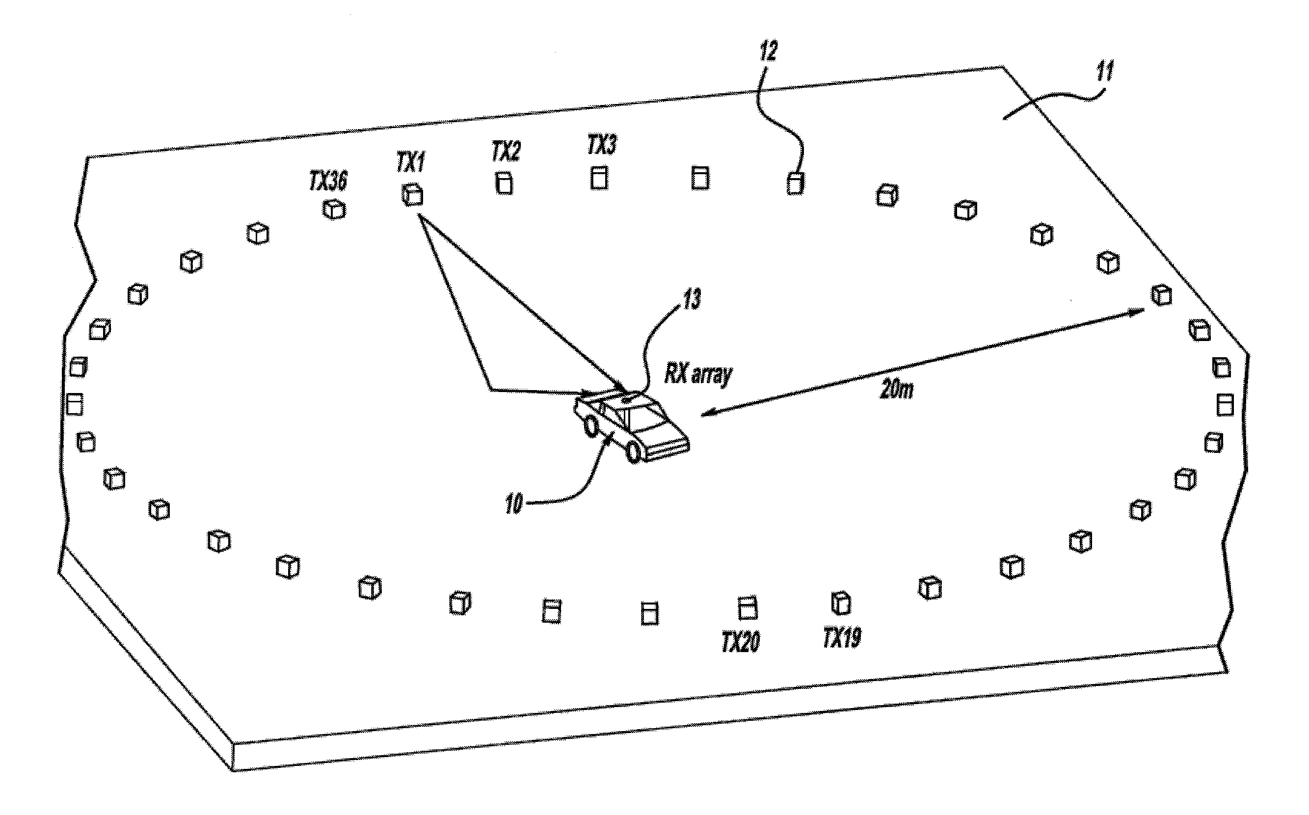
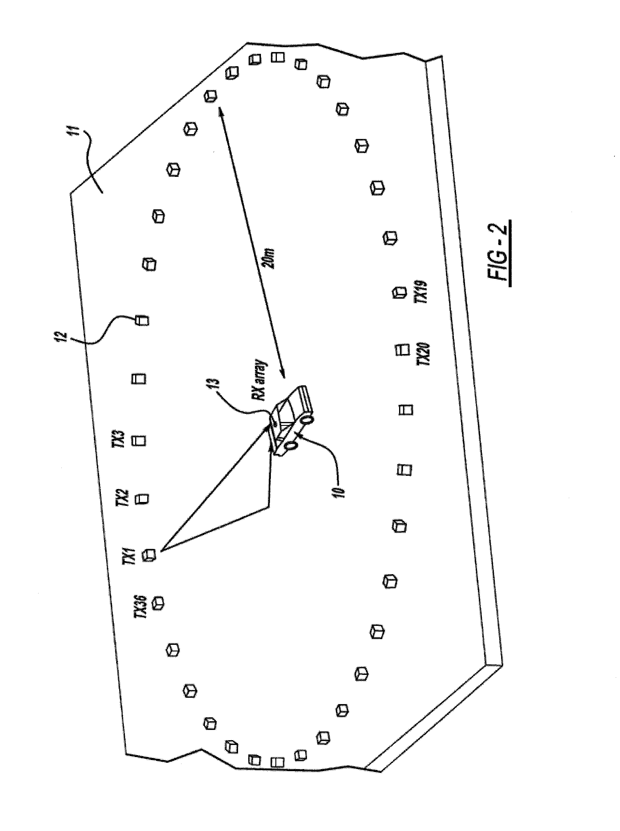
[0010]The microcontroller unit is adapted to receive digital data converted from the transmission signal, calculate a power level for each antenna in the array, sort the antennas according to each antenna's power level, and cause the antenna selected with the highest probability of receiving the transmitted signal to transmit a signal back to the transmission device to cause one of the plurality of indicators to turn on, wherein the indicator that is turned on is associated with the direction of the vehicle with respect to the transmission device. The system is operable to calculate a substantially accurate DOA in any environment selected from the group consisting of an open field, a parking lot filled with other vehicles, and a parking garage filled with other vehicles and having walls and other structures. The antennas can be adapted to operate at a half-power beam width (HPBW) of 45°, 90°, and 135°. The DOA estimates can fall within a threshold value ranging from about 22.5° to 67.5°. The system can achieve DOA estimates of at least 40% pass rate for a 22.5° threshold and at least 70% pass rate for 67.5° threshold in a parking garage or open parking environment.

Problems solved by technology

These systems have been unsuccessful in more complex reflecting environments such as parking lots and parking garages.

Method used


Image

  • Automotive direction finding system based on received power levels
  • Automotive direction finding system based on received power levels
  • Automotive direction finding system based on received power levels

Examples


Embodiment Construction

[0033]All patents, patent applications, government publications, government regulations, and literature references cited in this specification are hereby incorporated herein by reference in their entirety. In case of conflict, the present description, including definitions, will control.

DEFINITIONS

[0034]PD-DF—Pseudo-doppler direction finding[0035]PD—Pseudo-doppler[0036]DF—Direction finding[0037]RPL—Received power level method[0038]PLL—Phase locked loop[0039]COTS—Cost of the shelf[0040]DOA—Direction of arrival[0041]SBR—Shooting and bouncing rays[0042]SC-PD—Single channel pseudo-doppler[0043]AOA—Angle of arrival[0044]RF—Radio frequency[0045]IF—Intermediate frequency[0046]Hz, KHz, MHz, and GHz—Hertz, Kilohertz, Megahertz, and Gigahertz[0047]BPSK—binary phase shift keying[0048]LED—Light emitting diodes[0049]LOS—Line of sight[0050]A-SCPD—Analogue single channel pseudo-doppler[0051]D-PLL—Digital phase lock loop[0052]DFT—Discrete Fourier transform[0053]HPBW—Half-power beam widths[0054]ADC—...


PUM


Abstract

A system is provided for locating a vehicle. The system comprises a transmission device such as a key fob for transmission and receiving of a signal. Typically the key fob has a plurality of indicators such as LED indicators arranged in a circle. The key fob is adapted to transmit a radio frequency or microwave frequency transmission signal. An antenna array is positioned on or in a vehicle. The array comprises a plurality of antennas, generally arranged in a circular pattern. The array is adapted to receive the transmission signal from the transmission device which is converted to be analyzed by a microcontroller unit (MCU). The MCU is adapted to: (i) receive digital data converted from the transmission signal, (ii) calculate an angle of arrival (AOA) or direction of arrival (DOA) based on known components and an algorithm, and (iii) transmit a selection signal back to the key fob. A signal processing unit is coupled to the plurality of antennas and the MCU. The signal processing unit is adapted to receive the signal transmission from each antenna, convert the signal to digital data, and transmit the digital data to the MCU.

Description

CROSS-REFERENCE TO RELATED APPLICATIONS[0001]This application claims the benefit of U.S. Provisional Patent Application No. 61 / 283,822, filed Dec. 9, 2009, the disclosure of which is incorporated herein by reference in its entirety.STATEMENT REGARDING FEDERALLY SPONSORED RESEARCH OR DEVELOPMENT[0002]Non-applicableBACKGROUND OF THE INVENTION[0003](1) Field of the Invention[0004]The present disclosure relates to systems and methods for finding a vehicle.[0005](2) Description of Related Art[0006]Direction finding has been around for a long time. Some solutions depend on the determination of position via the Global Positioning System (GPS) at two points. The direction is computed from the position vector formed between the two points. Non-GPS based direction finding techniques have been tested that determine the direction of a radio frequency signal by receiving it through a circular array of antenna elements. Algorithms such as the Analog Single Channel (A-SCPD) and Digital Phase Lock ...

Claims


Application Information

Patent Timeline
IPC IPC(8): G08B5/22
CPCG08G1/123G01S3/54
Inventor ALOI, DANIEL N.SHARAWI, MOHAMMAD S.
Owner OAKLAND UNIVESITY
Learn More