Methods and systems for bounding box clipping

a technology of bounding box and clipping, applied in the field of methods and systems for bounding box clipping, can solve the problems of difficult economic recovery of natural resources such as oil, difficulty in determining the behavior of fluids across the boundary, and difference between a successful well and an uneconomical well

Active Publication Date: 2019-12-31
SCHLUMBERGER TECH CORP
View PDF9 Cites 0 Cited by
  • Summary
  • Abstract
  • Description
  • Claims
  • Application Information

AI Technical Summary

Problems solved by technology

The economic recovery of natural resources such as oil is extremely difficult.
Accurately predicting the flow in a reservoir for the production plan can make the difference between a successful well and an uneconomical well.
When different types of substrata meet (for example, at a discontinuity), determining the behavior of fluids across the boundary is problematic.
Known approaches are either costly and difficult to implement or inaccurately approximate a fault geometry.
However, this introduces numerical errors up to and including inadvertent modelling of non-physical behaviors.

Method used


Image

  • Methods and systems for bounding box clipping
  • Methods and systems for bounding box clipping
  • Methods and systems for bounding box clipping

Examples


Embodiment Construction

[0032]Reference will now be made in detail to embodiments, examples of which are illustrated in the accompanying drawings and figures. In the following detailed description, numerous specific details are set forth in order to provide a thorough understanding of the invention. However, it will be apparent to one of ordinary skill in the art that the invention may be practiced without these specific details. In other instances, well-known methods, procedures, components, circuits and networks have not been described in detail so as not to unnecessarily obscure aspects of the embodiments.

[0033]It will also be understood that, although the terms first, second, etc., may be used herein to describe various elements, these elements should not be limited by these terms. These terms are used to distinguish one element from another. For example, a first object or step could be termed a second object or step, and, similarly, a second object or step could be termed a first object or step, witho...


PUM


Abstract

A method is described in which a polyhedral grid representative of seismic data is provided. A polyhedral cell of the polyhedral grid is identified. A polyhedron that encloses the polyhedral cell is created. A region of the polyhedron to remove based on faces of the identified polyhedral cell is identified. The identified region of the polyhedron is removed. The identifying and removing are repeated for a plurality of faces of the identified polyhedral cell. A pressure center of the polyhedral cell is determined.

Description

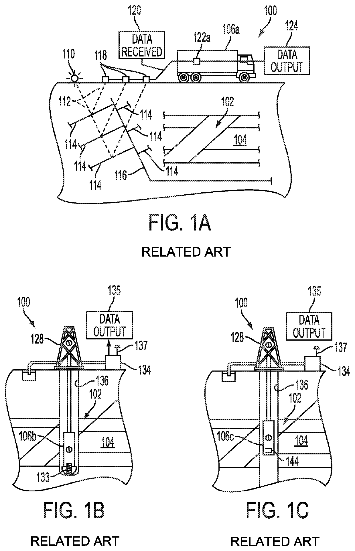
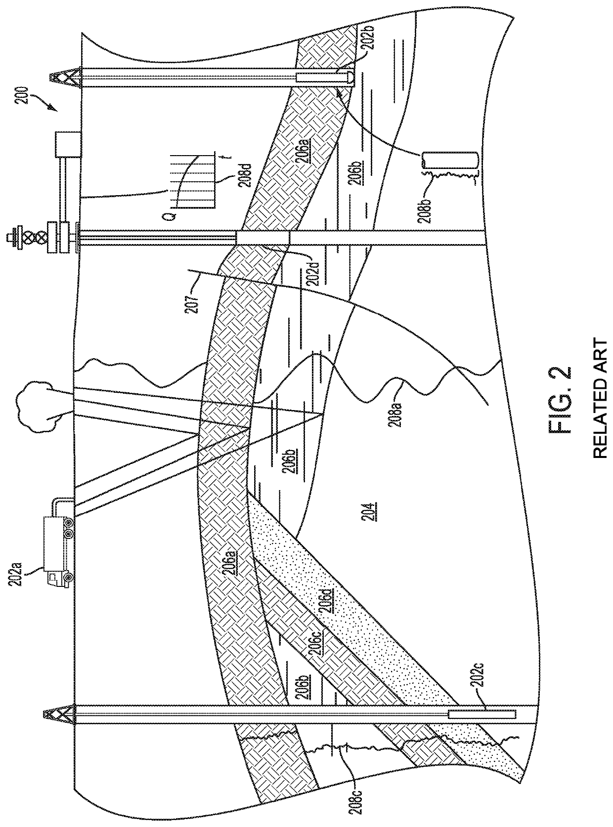
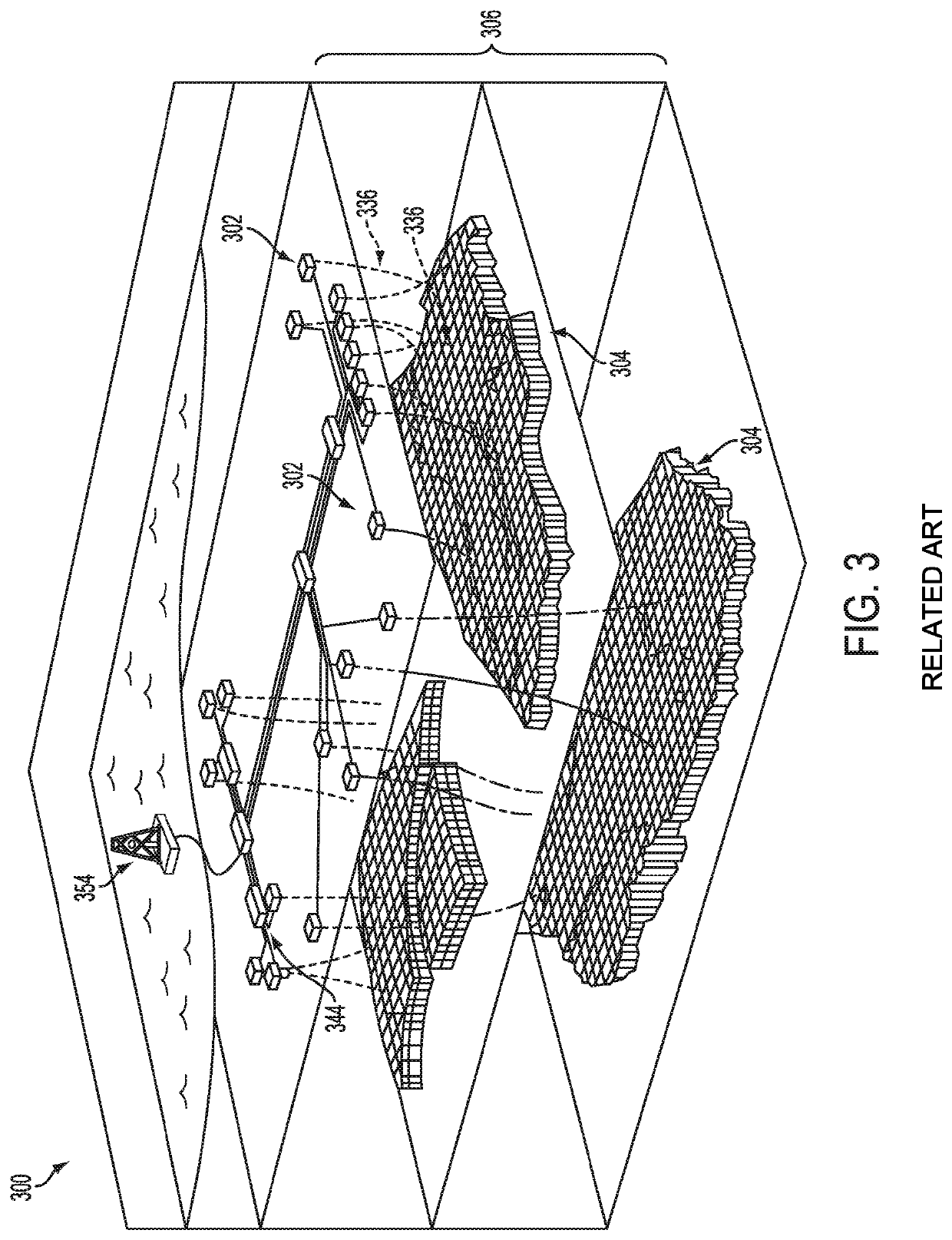
BACKGROUND[0001]The economic recovery of natural resources such as oil is extremely difficult. Prediction of the flow in a reservoir is important in determining a production plan. Accurately predicting the flow in a reservoir for the production plan can make the difference between a successful well and an uneconomical well.[0002]Seismic surveys may be used to collect rock and soil information that may in turn be used to locate faults and estimate fluid flow in the substrata. When different types of substrata meet (for example, at a discontinuity), determining the behavior of fluids across the boundary is problematic. Known approaches are either costly and difficult to implement or inaccurately approximate a fault geometry. In such prior techniques, estimations or assumptions may be used to fix the data such that a calculation can be completed. However, this introduces numerical errors up to and including inadvertent modelling of non-physical behaviors. In a grid based approach to mo...

Claims


Application Information

Patent Timeline
Patent Type & Authority Patents(United States)
IPC IPC(8): G06F17/50
CPCG06F17/5009G01V99/00G01V2210/642G06F30/20
Inventor VIARD, THOMAS LUCAS
Owner SCHLUMBERGER TECH CORP
Why Eureka
Try Eureka