Metal porous body and making method thereof, current collector for cell having same

A metal porous body, porous body technology, applied in battery electrodes, electrode carriers/current collectors, circuits, etc., can solve the problems of window size reduction, easy window blockage, cracks, etc., to achieve the effect of increasing capacity

Inactive Publication Date: 2004-10-13
SUMITOMO ELECTRIC IND LTD
View PDF0 Cites 0 Cited by
  • Summary
  • Abstract
  • Description
  • Claims
  • Application Information

AI Technical Summary

Problems solved by technology

[0008] However, using conventional methods to reduce the diameter of the substantially polyhedral cells results in a simultaneous reduction in the size of the windows present in the inner cells visible through the openings of the polyhedral cells on the sponge-like metal surface.
[0009] The problem caused by the reduction in the size of the window in the inner chamber is that the window is easily blocked during the process of filling the active material, and it is difficult to uniformly fill the active material into the sponge metal.
These problems will cause serious problems of cracks in the subsequent rolling process and reduce the final capacity of the battery

Method used


Image

  • Metal porous body and making method thereof, current collector for cell having same
  • Metal porous body and making method thereof, current collector for cell having same
  • Metal porous body and making method thereof, current collector for cell having same

Examples


example 1

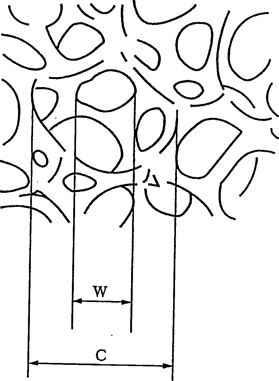
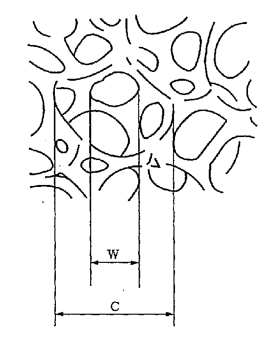
[0083] A polyurethane foam material with a thickness of 1.0 mm was used as the core. The foam has a continuous microcellular structure with cells with an average diameter of 260 microns and windows with an average diameter of 110 microns.

[0084] The core is processed through the following process to obtain a nickel coating amount of 10g / m 2 conductive porous body.

[0085] (1) degreasing treatment;

[0086] (2) washing treatment;

[0087] (3) Sensitization treatment;

[0088] (4) activation treatment;

[0089] (5) washing treatment;

[0090] (6) Electroless nickel plating treatment.

[0091] Table 1 shows the chemicals and treatment conditions used in the above (1)-(6) treatments.

[0092] serial number

deal with

chemicals

Processing temperature (℃)

Processing time (minutes)

chemicals

concentration

1

skim

Alkaline Degreaser*

100g / l.

50

10

2

washed

-

-

...

example 2

[0096]The coating liquid was prepared by the method described below. First, polyvinyl alcohol and phenolic resin were dissolved in ethanol at a weight ratio of 7:3. Then, the graphite powder with an average particle size of 0.8 μm was dispersed in the ethanol solution to make the solution concentration reach 100 g / liter. The prepared coating liquid was applied to the frame surface of the same polyurethane foam core as that used in Example 1 by the dip coating method. The coated cores were dried at 100°C. In this way, it is obtained that the coating amount is 50g. / m 2 The conductive porous body of the conductive layer.

[0097] This conductive porous body, in Watts plating tank, with this conductive porous body as cathode, at 10A / dm 2 Electroplating for 20 minutes under the current density (nickel plating). The plated porous body was heat-treated in a hydrogen atmosphere at 1000° C. for 30 minutes to remove the polyurethane foam core. Thus, a metal porous body was obtaine...

example 3

[0099] A polyurethane foam with a thickness of 1.0 mm was used as the core. The foam has a continuous microcellular structure with cells with an average diameter of 310 microns and windows with an average diameter of 122 microns. By the same treatment as in Example 1, a metal porous body was obtained.


PUM


Abstract

A metallic porous body that is free from clogging in the filling process of an active material, that allows the active material to fill the body uniformly even to the deep inside, and that thereby enables a secondary battery to combine large battery capacity and a high output; a method of manufacturing the metallic porous body; and a current collector having the metallic porous body. The metallic porous body is composed of a metallic framework having a three-dimensional network with a continuous-pore structure formed by linking substantially polyhedral cells. The substantially polyhedral cells have an average cell diameter of 200 to 300 µ m and an average window diameter of 100 to 200 µm. The metallic porous body can be obtained by the following method, for instance: First, a plastic porous body is provided that has an average cell diameter of 200 to 300 µm and an average window diameter of 100 to 200 µm. Second, a conductive layer is formed on the surface of the framework of the plastic porous body to produce a conductive porous body having a resistivity of 1 k©·cm or less. Finally, a continuous metalplated layer is formed on the surface of the conductive layer by electroplating, with the conductive porous body serving as the cathode. The above-mentioned current collector is provided by filling an active material into the pores of the metallic porous body.

Description

technical field [0001] The present invention relates to a metal porous body including a metal frame for alkaline batteries (such as nickel-cadmium batteries, nickel-hydrogen batteries and nickel-zinc batteries) and a method for manufacturing the metal porous body, and a metal porous body having the same current collector. Background technique [0002] As current collectors for alkaline batteries, sponge metals and sintered metals are widely used. [0003] Sponge metals are composed of a metal framework having a three-dimensional network structure with a continuous microporous structure formed by connecting cells that are substantially polyhedral. Because the porous metal has a porosity as high as 90%-98%, the amount of active material charged per unit volume can be increased; therefore, the advantage is that the current collector can have a high capacity density (mAh / cc). [0004] The porosity of sintered metal is not greater than about 85%, which is worse than that of spo...

Claims


Application Information

Patent Timeline
IPC IPC(8): B22F3/11B22F5/00C25D5/56H01M4/80
CPCC25D5/56H01M4/808H01M2300/0014H01M4/80Y10T428/12042Y10T428/12111Y02E60/10
Inventor 假家彩生林宪器稻泽信二真嶋正利
Owner SUMITOMO ELECTRIC IND LTD
Why Eureka
Try Eureka