
System and method of grid generation for discrete fracture modeling

a grid and discrete fracture technology, applied in the field of system and method for generating grids, can solve the problems of difficult hydrocarbons to pass through formation, gridding strategies for conventional reservoir simulations are typically not designed to handle a large number of internal geometric features, and gridding strategies are only suitabl

Active Publication Date: 2010-06-03
CHEVROU USA INC
View PDF25 Cites 36 Cited by
  • Summary
  • Abstract
  • Description
  • Claims
  • Application Information

AI Technical Summary

Problems solved by technology

Highly complex geological subsurface reservoirs, such as reservoirs having a network of fractures, present unique and specialized challenges with regards to reservoir simulation.
Subsurface reservoirs with a network of fractures typically have a low permeability rock matrix, making it difficult for hydrocarbons to pass through the formation.
For fractured subsurface reservoirs, gridding poses a unique challenge due to the geometric complexity and stochastic nature of the network of fractures.
For instance, gridding strategies for conventional reservoir simulations are typically not designed to handle a large number of internal geometric features, such as fractures.
Many gridding strategies are only suitable for geometries that are well connected and do not contain cracks or overlaps, which are often referred to as “water-tight” geometries.
Others gridding strategies are unable to achieve good grid quality while capturing certain geometric intricacies, such as one fracture slightly penetrating the plane of another fracture, two fractures being close to one another without intersecting, or two fractures intersecting with a small dihedral angle.
If reservoir gridding techniques are not able to accommodate these fine-details while maintaining good grid quality, simulation of the model can result in reduced accuracy, increased run times, convergence problems, or a combination thereof.
However, one skilled in the art will recognize that this is not straightforward as removal of one problem often creates another.
In addition, the implementation of these past attempts is nontrivial due to considerations of floating-point arithmetic in calculating fracture intersections.

Method used


Image

  • System and method of grid generation for discrete fracture modeling
  • System and method of grid generation for discrete fracture modeling
  • System and method of grid generation for discrete fracture modeling

Examples


examples

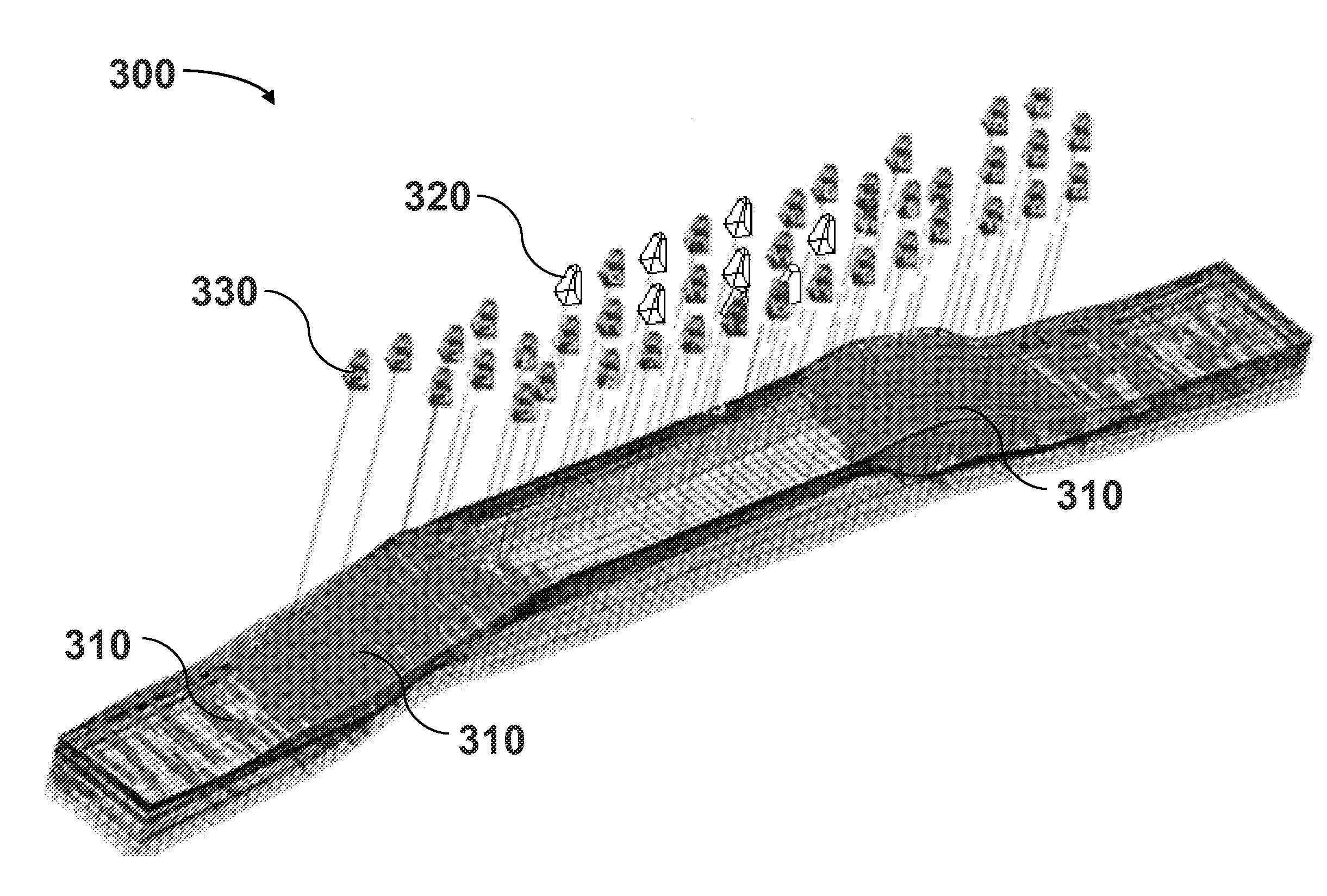
[0055]FIG. 6A is an example that illustrates domain 200 depicting a fractured subsurface reservoir having two horizontal layers (not shown) and fracture representation 201. Domain 200 contains 40 discrete fractures 203 that are represented by 2D polygons. In this example, the fractures within fracture representation 201 are represented as planar rectangles extending within the horizontal layers. Fractures penetrating through both horizontal layers of domain 200 extend from the bottom of domain 200 to the top of domain 200. Fracture 205 represents a fracture bound by the top horizontal layer, fracture 207 represents a fracture bound by the bottom horizontal layer, and fracture 209 penetrates through both horizontal layers such that it extends from the bottom of domain 200 to the top of domain 200. Domain 200 is an example of a domain that can be provided in Step 11 of method 10 and Step 21 of method 20.

[0056]FIG. 6B shows the interfaces of the polyhedral cells 211 that were selected ...


PUM


Abstract

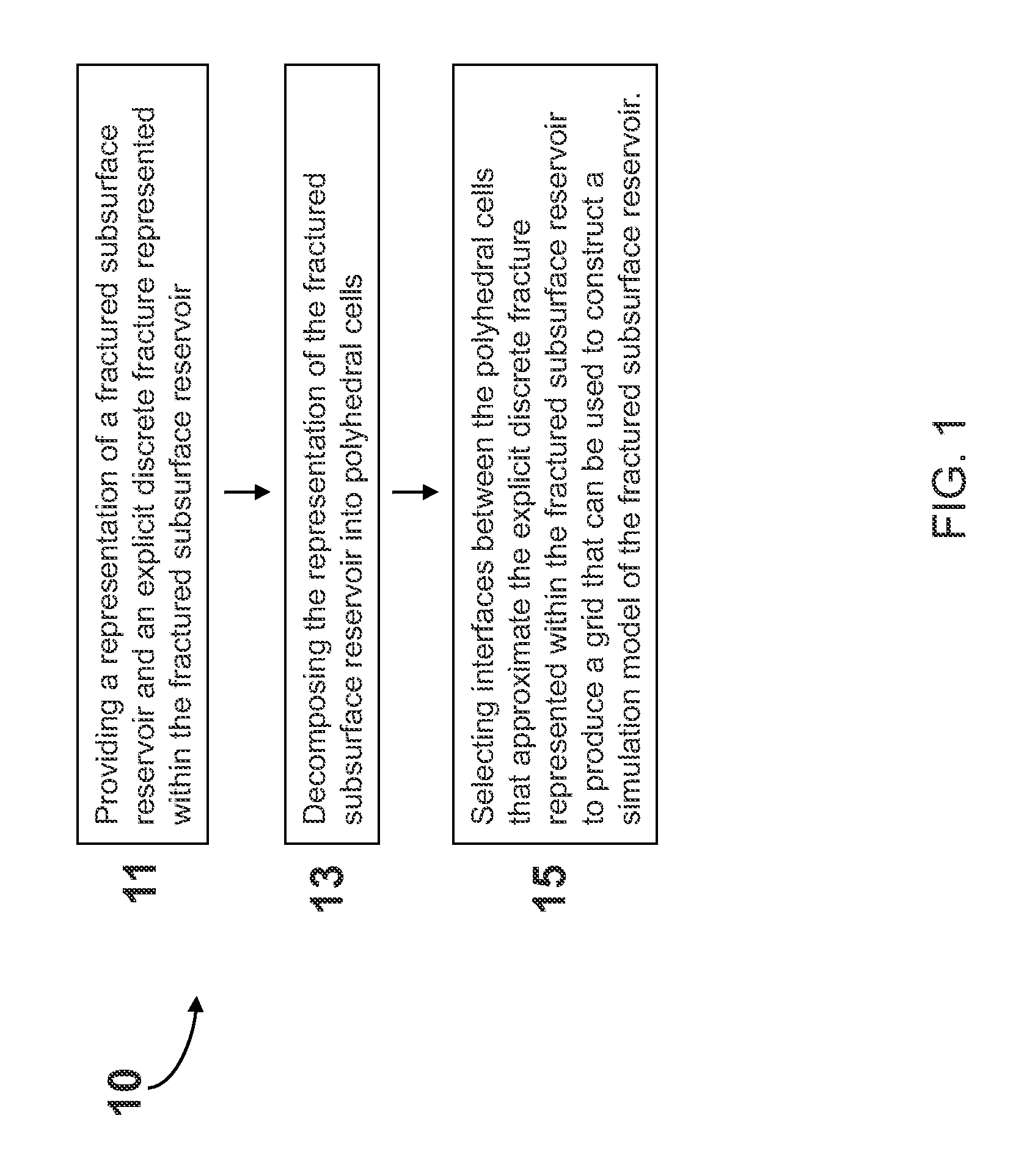
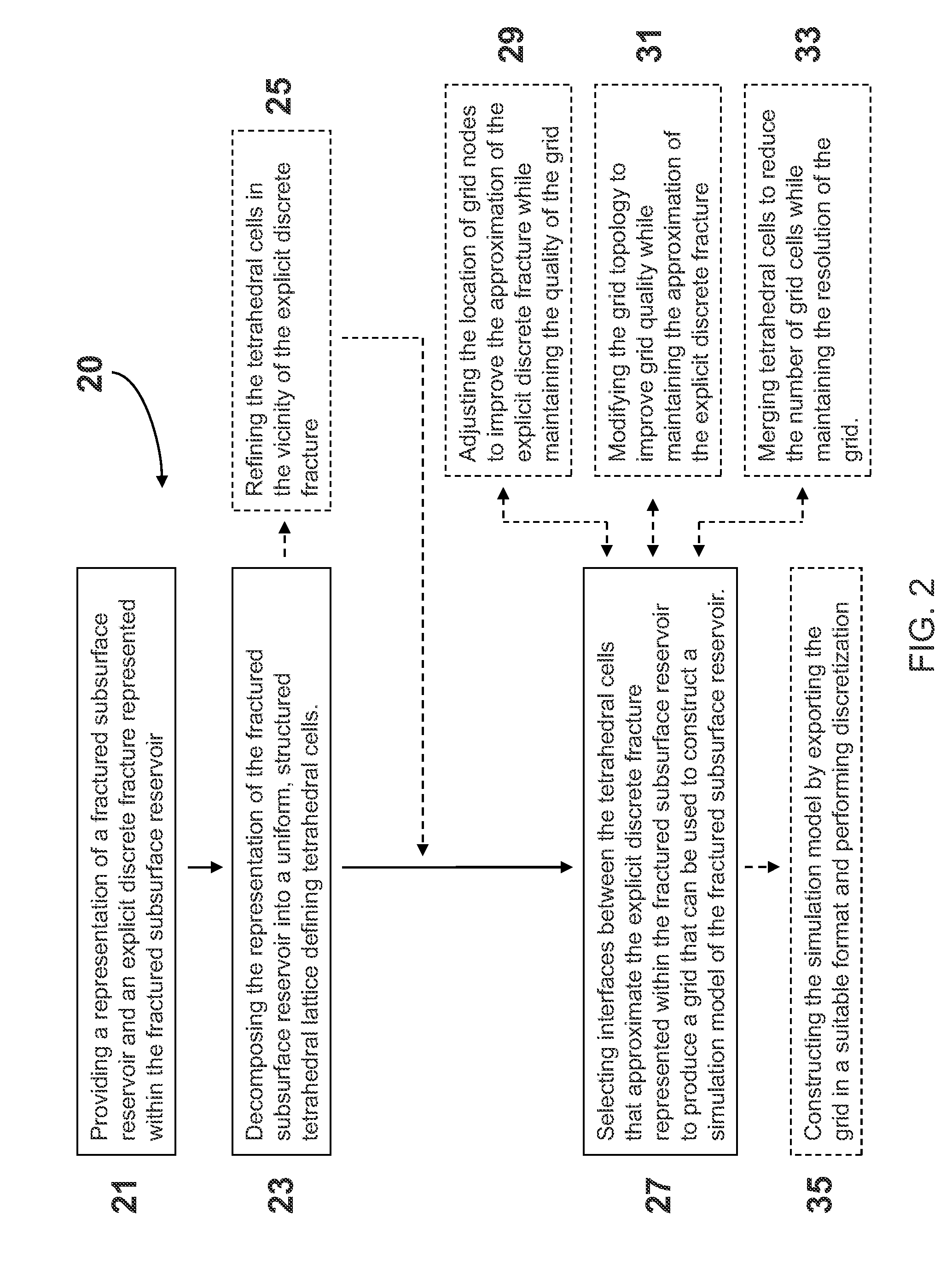
Computer-implemented systems and methods are provided for generating accurate grids that can be used for simulation of highly complex subsurface reservoirs, such as fractured subsurface reservoirs. A representation of a fractured subsurface reservoir and an explicit discrete fracture represented within the fractured subsurface reservoir are provided. The representation of the fractured subsurface reservoir is decomposed into polyhedral cells. Interfaces between the polyhedral cells are selected to approximate the discrete fracture explicitly represented within the fractured subsurface reservoir. The selected interfaces are used to produce a grid that can be used for constructing a simulation model of the fractured subsurface reservoir.

Description

CROSS-REFERENCE TO RELATED APPLICATION[0001]The present application for patent claims the benefit of United States Provisional application for patent bearing Ser. No. 61 / 119,604, filed on Dec. 3, 2008, which the entirety of the application is incorporated herein by reference.FIELD OF THE INVENTION[0002]The present invention generally relates to a system and method for generating a grid that can be used to construct a simulation model of a subsurface reservoir, and more particularly, to a system and method for generating a grid that can be used to construct a simulation model of a highly complex subsurface reservoir such as a fractured subsurface reservoir.BACKGROUND OF THE INVENTION[0003]The field of hydrocarbon production is directed to retrieving hydrocarbons that are trapped in subsurface reservoirs. Typically, these reservoirs are comprised of parallel layers of rock and fluid material each characterized by different sedimentological and fluid properties. Hydrocarbons accumulate...

Claims


Application Information

Patent Timeline
Patent Type & Authority Applications(United States)
IPC IPC(8): G06G7/48G06T17/05
CPCE21B43/00G01V1/18G06F2217/16G01V2210/66G06F17/5018G01V11/00G06F30/23G06F2111/10
Inventor MALLISON, BRADLEY THOMASHUI, MUN-HONG
Owner CHEVROU USA INC
Learn More