
Acoustic liners with oblique cellular structures

a technology of cellular structure and acoustic liners, which is applied in the field of acoustic structures, can solve the problems of increasing the size and weight of acoustic liners, affecting the sound quality of acoustic liners,

Active Publication Date: 2019-09-05
GENERAL ELECTRIC CO
View PDF10 Cites 21 Cited by
  • Summary
  • Abstract
  • Description
  • Claims
  • Application Information

AI Technical Summary

Benefits of technology

This patent is about a new type of material used in audio liner and how it can be formed into layers using strips that create a honeycomb-like structure. The material can be designed to offer maximum flexibility in treating sound. The finished layer has tiny cells that are arranged in various ways to provide specific sound patterns. This design can provide better sound absorption and reduce sound echo.

Problems solved by technology

Aircraft engine noise can be a problem in high population areas and noise-controlled environments.
The noise generally includes contributions from various source mechanisms in the aircraft, with fan noise typically being a dominant component of the noise at take-off and landing.
However, high-bypass turbofan engines tend to emanate more sound at low frequencies, which calls for correspondingly deeper cellular structures that tend to increase the size and weight of acoustic liners.
Efforts to dampen or attenuate sound across the range of frequencies generated by turbofan engines face the problem of minimizing the size and weight of the acoustic liners while still providing sufficient noise reduction over a range of sound frequencies.
These additional cellular layers, however, tend to be heavier and more complicated and expensive to produce relative to single-degree-of-freedom liners which have only a single cellular layer.
However, these variable depth structures require a thicker core layer to accommodate the deeper individual cells and also are more expensive and complicated to produce.
Additionally, the cells that have shorter depths typically have excess solid material between the bottom of the cell and the back sheet, which also adds to the overall weight of the cellular layer.

Method used


Image

  • Acoustic liners with oblique cellular structures
  • Acoustic liners with oblique cellular structures
  • Acoustic liners with oblique cellular structures

Examples


Embodiment Construction

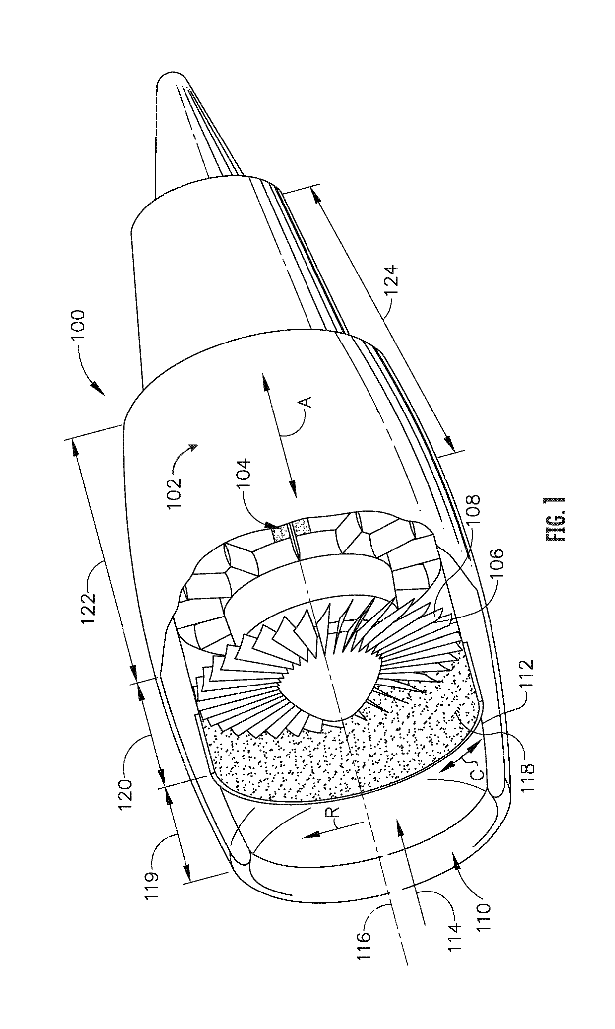
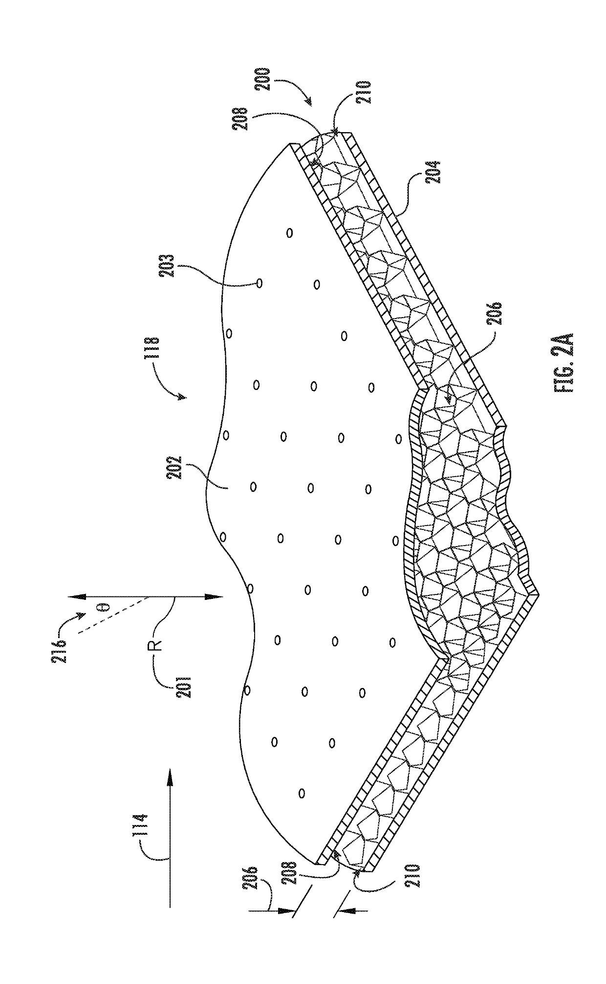
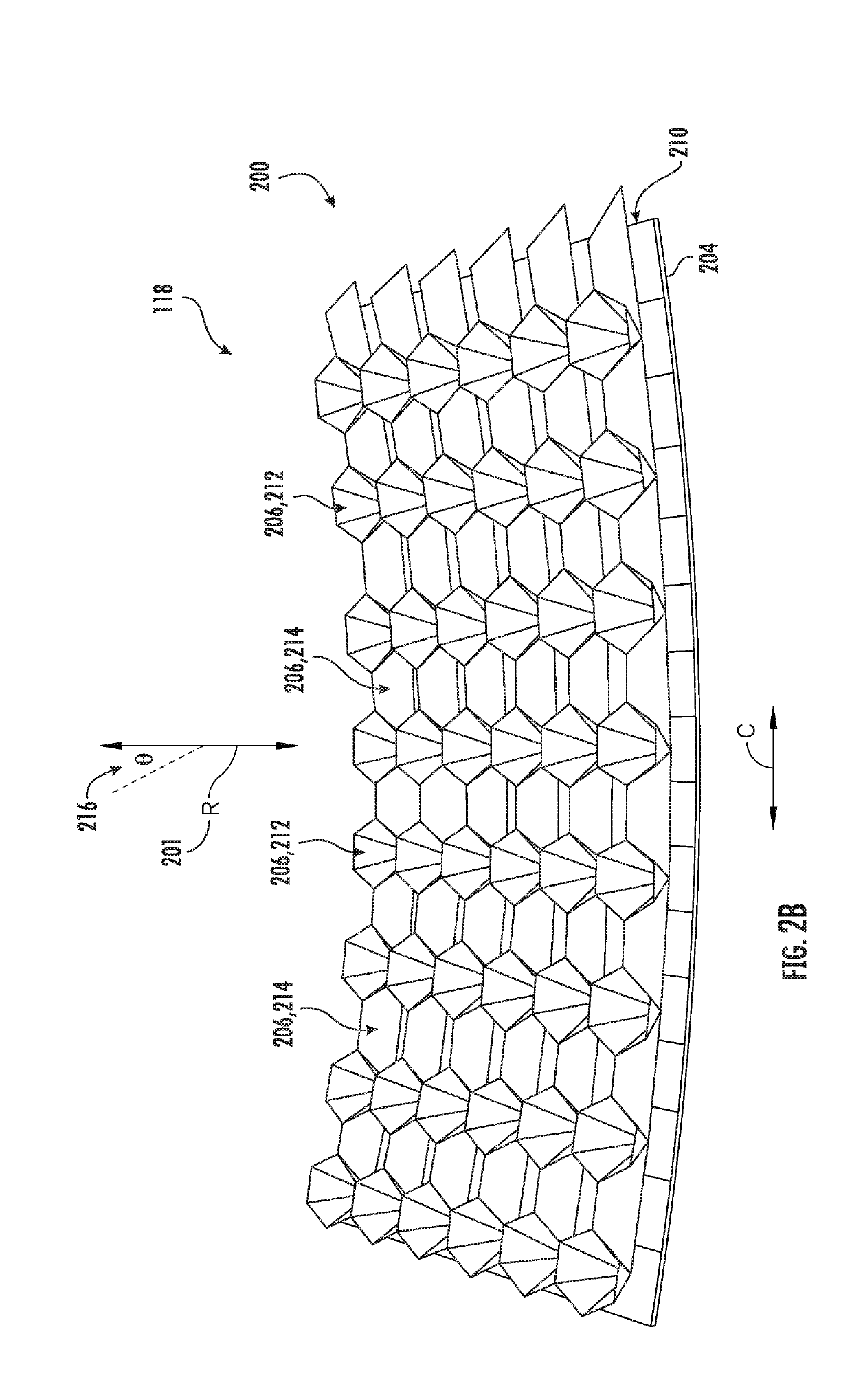
[0050]Various aspects and features are described below in greater detail with reference to the appended figures, including among other things, exemplary acoustic liners, core layers for acoustic liners with oblique polyhedral cellular structures, turbomachines that utilize such acoustic liners, and related acoustic dampening and attenuation systems and methods. Numerous specific details are set forth in order to provide a thorough understanding of the presently disclosed subject matter. It will be apparent, however, to those skilled in the art, that the presently disclosed subject matter may be practiced without some or all of these specific details. In other instances, well known aspects and features have not been described in detail in order to not unnecessarily obscure the present disclosure. Those skilled in the art will also appreciate that various modifications and variations can be made to the disclosed subject matter without departing from the spirit and scope of the present...


PUM

PropertyMeasurementUnit
convergence angleaaaaaaaaaa

Abstract

The present disclosure provides acoustic structures and related systems and methods which may be used to dampen or attenuate sound waves, including, for example, noise generated by or emanating from various aspects or components of turbomachines such as turbine engines. These acoustic structures include oblique polyhedral cellular structures, including converging polyhedral cells and diverging polyhedral cells, and related systems and methods of making and using such acoustic structures.

Description

FIELD[0001]The present disclosure generally relates to acoustic structures and related systems and methods which may be used to dampen or attenuate sound waves, including, for example, noise generated by or emanating from various aspects or components of turbomachines such as turbine engines. More particularly disclosed herein are acoustic structures that include oblique polyhedral cellular structures, including cellular structures providing continuous degree of freedom acoustic treatments, and related systems and methods of making and using such acoustic structures.BACKGROUND[0002]Aircraft engine noise can be a problem in high population areas and noise-controlled environments. The noise generally includes contributions from various source mechanisms in the aircraft, with fan noise typically being a dominant component of the noise at take-off and landing. Fan noise propagates through the engine intake duct, and then emanates to the outside environment. Acoustic structures such as l...

Claims


Application Information

Patent Timeline
Patent Type & Authority Applications(United States)
IPC IPC(8): B64C1/06B64C1/40G10K11/172F02K1/82E04B1/86
CPCB64C1/066B64C1/40G10K11/172F02K1/827E04B2001/8476B29L2031/3076B29L2007/002E04B2001/748E04B2001/8428E04B1/86F02C7/045B64D2033/0206F05D2250/323F05D2250/324G10K11/168B64D33/02Y02T50/60
Inventor CEDAR, RICHARD DAVIDSIEKMAN, MICHAEL WILLIAM
Owner GENERAL ELECTRIC CO
Learn More