Method to reduce torque ripple of permanent magnet synchronous motor

a synchronous motor and permanent magnet technology, applied in the direction of torque ripple control, etc., can solve the problems of increasing the cost of production, limiting the application of these motors, and vibration of the stator core, so as to ease vibration and nois

Active Publication Date: 2020-01-07
JIANGSU UNIV
View PDF9 Cites 0 Cited by
  • Summary
  • Abstract
  • Description
  • Claims
  • Application Information

AI Technical Summary

Benefits of technology

[0047]a) In the disclosure, the magnet shifting method not only reduces the torque ripple component caused by cogging torque, but also effectively reduces the torque ripple caused by permanent magnet torque or reluctance torque. Also, optimization of back-EMF and reduction of output torque ripple can significantly improve the stability of permanent magnet synchronous motors.
[0048]b) In the disclosure, the magnet shifting method comprehensively considers the minimum number of magnetic poles in each basic repeating unit that produces total torque (N0) and the minimum number of magnetic poles in each basic repeating unit that produces partial torque ripple component (Ni0). Under the premise of reducing torque ripple significantly, the average output torque is maintained to be nearly the same as the original value.
[0049]c) In the disclosure, the magnet shifting method contains different choices of shifted repeating units. According to the main source of torque ripple, the shifted repeating unit can be reasonably chosen so that different kinds of motors can achieve similar and effective results.
[0047]a) In the disclosure, the magnet shifting method not only reduces the torque ripple component caused by cogging torque, but also effectively reduces the torque ripple caused by permanent magnet torque or reluctance torque. Also, optimization of back-EMF and reduction of output torque ripple can significantly improve the stability of permanent magnet synchronous motors.
[0047]a) In the disclosure, the magnet shifting method not only reduces the torque ripple component caused by cogging torque, but also effectively reduces the torque ripple caused by permanent magnet torque or reluctance torque. Also, optimization of back-EMF and reduction of output torque ripple can significantly improve the stability of permanent magnet synchronous motors.

Problems solved by technology

However, due to the concavity and convexity of motor structure and the coupling effect of magnetic field, permanent magnet synchronous motors suffer from relatively large torque ripple, which limits the application of these motors.
However, the skewed stator or rotor is harder to build as for manufacturing, which also increases the cost of production.
This means that the improper selection of the fractional slot can lead to the vibration of the stator core.
These studies result in asymmetric magnets or change the distribution of magnets by poles shifting or other methods.
However, these methods only consider the reduction for cogging torque while ignoring the effects of reluctance torque on torque smoothness in inset and interior permanent magnet synchronous motors.
The total torque ripple was not always reduced effectively with an acceptable torque loss by the conventional magnet shifting.

Method used


Image

  • Method to reduce torque ripple of permanent magnet synchronous motor
  • Method to reduce torque ripple of permanent magnet synchronous motor
  • Method to reduce torque ripple of permanent magnet synchronous motor

Examples


Embodiment Construction

[0065]With reference to the appended drawings in the embodiment of the disclosure, the detailed embodiment of the disclosure is clearly and completely described in the following.

[0066]The following embodiments are for example only and not as a limitation to the disclosure.

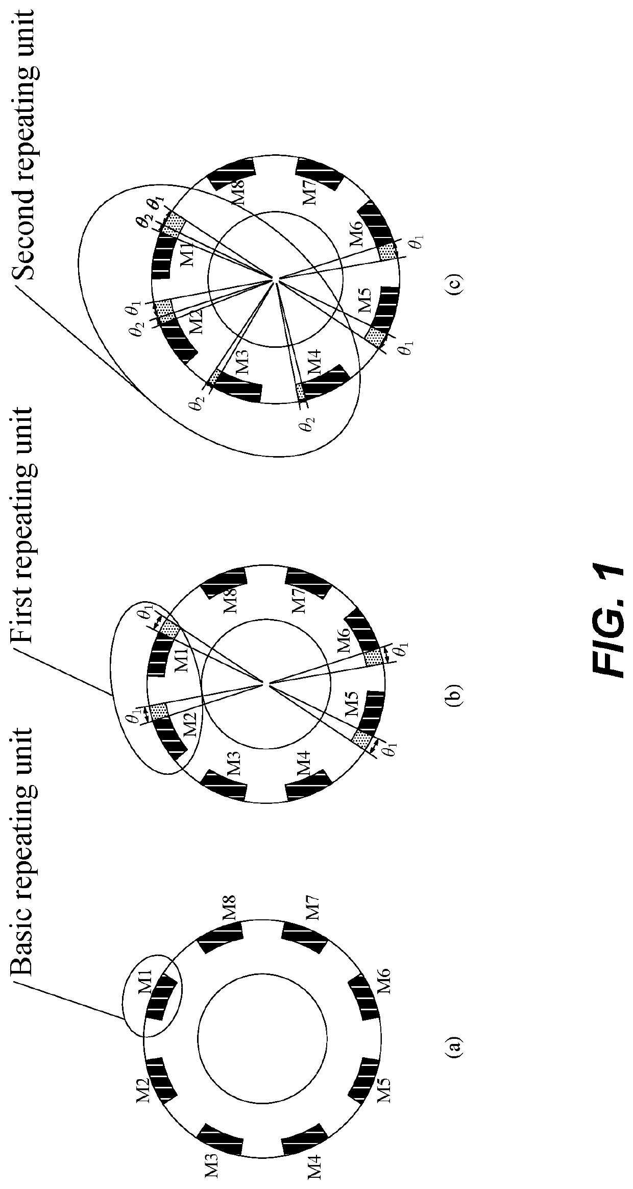
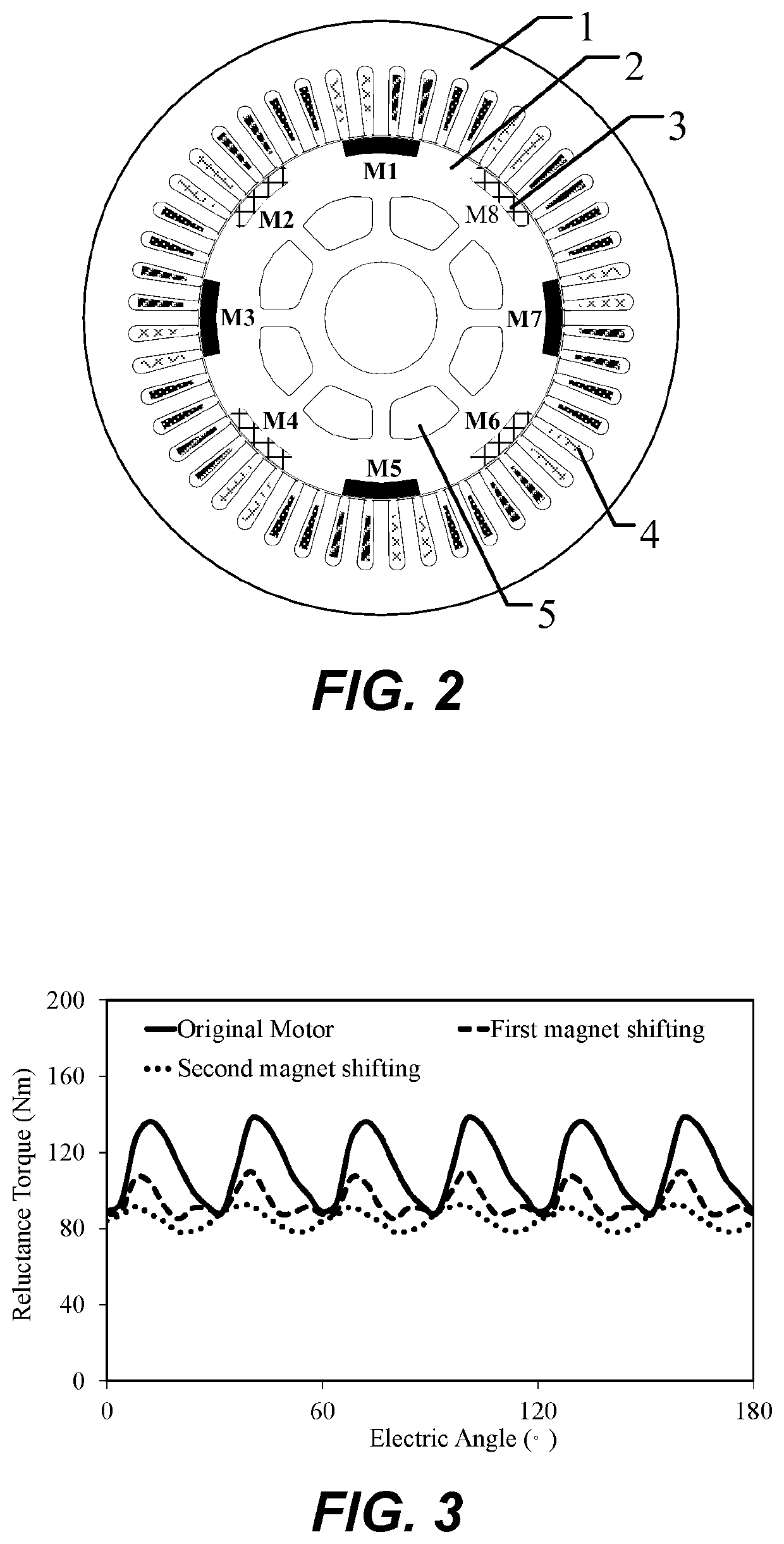
[0067]As shown in FIG. 2, an inset-mounted permanent magnet synchronous motor with three phases comprising an outer stator (1) and an inner rotor (2). The outer stator (1) includes forty-eight stator slots and embedded armature windings (4), and the inner rotor (2) includes a rotor core, eight magnetic poles (3) and six ventilation holes (5).

[0068]A three-phase inset-mounted permanent magnet synchronous motor is taken as an example, whose implementation steps are shown in FIG. 12.

[0069]1) Torque of target motor with different combination between poles and slots is analyzed. According to the relationship between the number of poles and slots, the fluctuation period number of torque ripple in one electric cycle is ca...


PUM


Abstract

A method named as Magnet Shifting to reduce torque ripple of permanent magnet synchronous motor is disclosed. A way of reasonably choosing the repeating unit of magnetic pole, the shifting ways and the shifting angle calculation of the first and second magnet shifting is described, which are carried on the repeating unit of magnetic poles individually or repeatedly to improve the performance of the motor. The method can be applied to surface, surface-inset and inner-embedded permanent magnet motors, which can reduce torque ripple caused by different torque components, including cogging torque, reluctance torque or permanent magnet torque. It also can quickly calculate the shifting angle of the magnetic pole by choosing repeating unit reasonably. Magnet shifting can effectively enhance the sinusoidal degree of back electrodynamic force (back-EMF) waveform, where the repeating units can offset the torque ripple between the maximum and the minimum value to reduce the different torque harmonics. Also, the output torque can be maintained nearly to the original value while less vibration noise of the motor is inevitably introduced.

Description

CROSS-REFERENCE TO RELATED APPLICATIONS[0001]This application is a national phase entry under 35 U.S.C. § 371 of International Patent Application PCT / CN2017 / 072924, filed Feb. 6, 2017, designating the United States of America, which claims the benefit under Article 8 of the Patent Cooperation Treaty to Chinese Patent Application Serial No. 201611066962.2, filed Nov. 29, 2016.TECHNICAL FIELD[0002]The application relates to the technology of permanent magnet synchronous motors, in particular, for reducing torque ripple of permanent magnet synchronous motors, which belongs to the field of motor manufacturing.BACKGROUND[0003]Permanent magnet synchronous motors have been widely used in various occasions due to their high efficiency and high torque density. Meanwhile, permanent magnet synchronous motors utilize magnetic material with high magnetic energy, instead of traditional excitation winding. This not only avoids the negative effects resulting from traditional excitation winding, but...

Claims


Application Information

Patent Timeline
Patent Type & Authority Patents(United States)
IPC IPC(8): H02P6/10
CPCH02P6/10
Inventor LIU, GUOHAIDU, XINXINZHAO, WENXIANGCHEN, QIANHU, DESHUI
Owner JIANGSU UNIV
Why Eureka
Try Eureka