Supercharge Your Innovation With Domain-Expert AI Agents!

System and method for converting heat to kinetic energy

a technology of heat and kinetic energy, applied in the field of conversion of heat to kinetic energy, can solve the problems of radioactive waste emitted huge amounts of heat, widespread waste of energy, and large amount of heat released into the environment without conversion,

Active Publication Date: 2020-01-14
ROBINSON SHAWN
View PDF8 Cites 0 Cited by
  • Summary
  • Abstract
  • Description
  • Claims
  • Application Information

AI Technical Summary

Benefits of technology

The system effectively converts heat into kinetic energy, providing a clean and sustainable energy source by harnessing waste heat from diverse sources, including radioactive waste, while ensuring environmental safety and operational efficiency.

Problems solved by technology

In addition, wasted energy is commonplace.
For example, many manufacturing processes (e.g. smelting) may release vast amounts of heat into the environment without converting the heat to a usable form of power (e.g. electricity).
In another example, radioactive waste may emit huge amounts of heat in the form of nuclear particles and waves that are not harnessed and converted into usable forms of power.

Method used


Image

  • System and method for converting heat to kinetic energy
  • System and method for converting heat to kinetic energy
  • System and method for converting heat to kinetic energy

Examples


Embodiment Construction

[0014]As used herein, unless used otherwise, the following term has the following meaning:

[0015]A “mechanism” refers to any device(s), process(es), routine(s), service(s), or combination thereof. A mechanism may be implemented in hardware, software, firmware, using a special-purpose device, or any combination thereof. A mechanism may be integrated into a single device or it may be distributed over multiple devices. The various components of a mechanism may be co-located or distributed. The mechanism may be formed from other mechanisms. In general, as used herein, the term “mechanism” may thus be considered to be shorthand for the term device(s) and / or process(es) and / or service(s).

[0016]The following detailed description is not intended to limit the current invention. Alternate embodiments and variations of the subject matter described herein will be apparent to those skilled in the art.

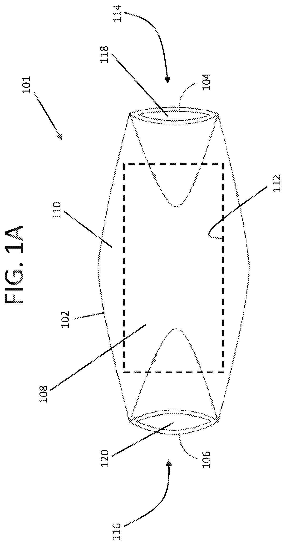
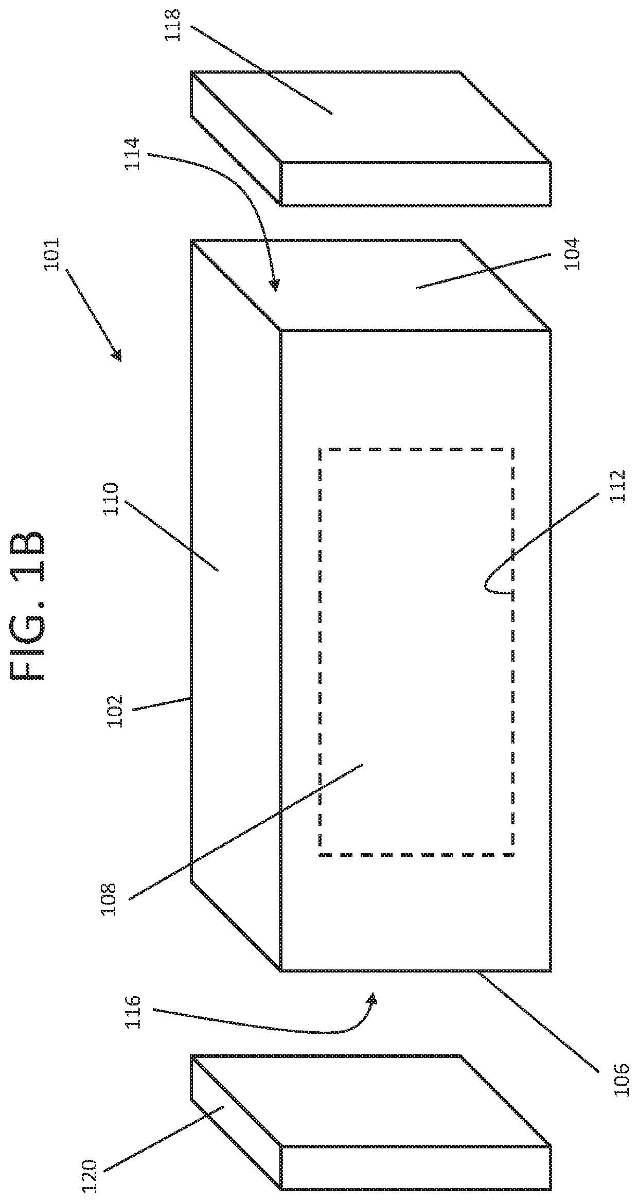
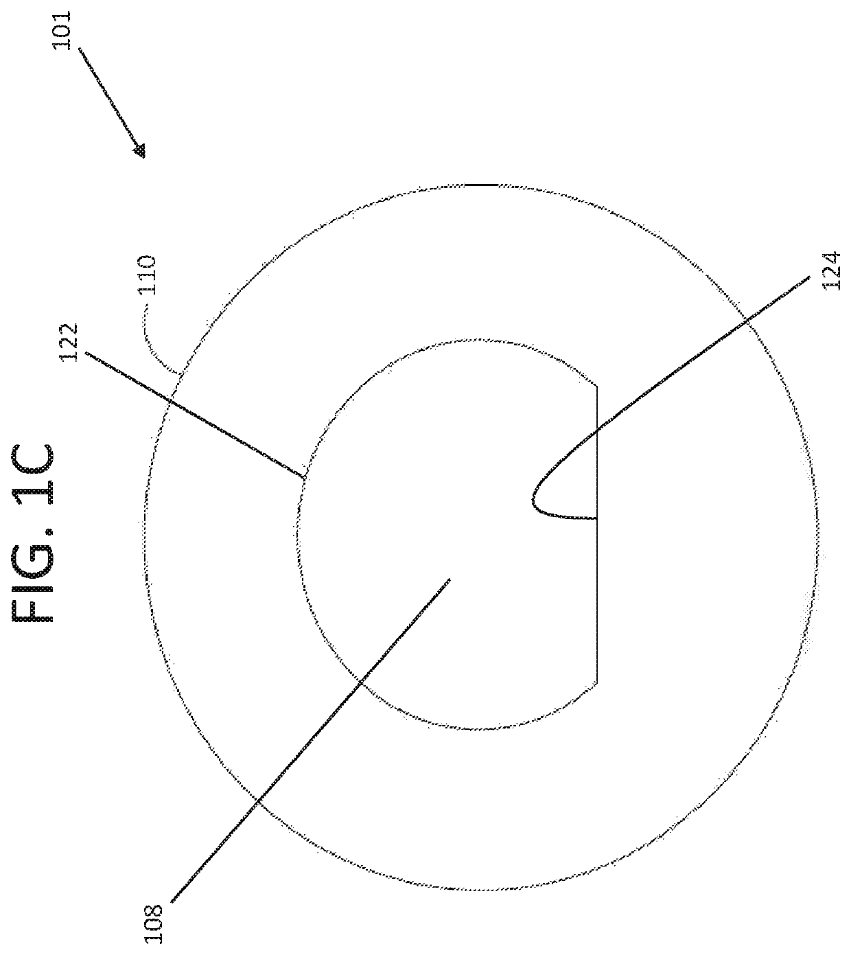
[0017]System 10 according to exemplary embodiments hereof is described with reference to FIGS. 1A...


PUM


Abstract

A system for converting heat to kinetic energy is disclosed. The system may include a heat source, bimetallic bands and wheels that may support the bimetallic bands. The bimetallic bands may be heated by the heat source and may rotate the wheels. The rotation of the wheels may then be used to convert the kinetic energy to power.

Description

CROSS REFERENCE TO RELATED APPLICATIONS[0001]This application is a continuation in part of U.S. patent application Ser. No. 15 / 205,609, filed Jul. 8, 2016, the entire contents of which are hereby fully incorporated herein by reference for all purposes.FIELD OF THE INVENTION[0002]The current invention generally relates to the conversion of heat to kinetic energy, and in particular to the use of bimetal bands to convert heat to kinetic energy.BACKGROUND OF THE INVENTION[0003]It is a well-known fact that clean sources of energy are needed to help protect the environment while supplying energy to those who require it. Examples of clean energy may include solar power, wind power and other types of clean energy.[0004]In addition, wasted energy is commonplace. For example, many manufacturing processes (e.g. smelting) may release vast amounts of heat into the environment without converting the heat to a usable form of power (e.g. electricity). In another example, radioactive waste may emit ...

Claims


Application Information

Patent Timeline
Patent Type & Authority Patents(United States)
IPC IPC(8): F03G7/06G21H3/00F16H7/02
CPCG21H3/00F03G7/06F16H7/02
Inventor ROBINSON, SHAWN
Owner ROBINSON SHAWN
Features
  • R&D
  • Intellectual Property
  • Life Sciences
  • Materials
  • Tech Scout
  • Unparalleled Data Quality
  • Higher Quality Content
  • 60% Fewer Hallucinations
Learn More