Liquid crystal display

a liquid crystal display and display screen technology, applied in static indicating devices, instruments, non-linear optics, etc., can solve the problems of insufficient space between the test pad and the signal line, and achieve the effect of reducing the size of the outside portion, minimizing the inflow of static electricity, and easy alignment of the pad

Active Publication Date: 2020-01-14
TCL CHINA STAR OPTOELECTRONICS TECH CO LTD
View PDF16 Cites 0 Cited by
  • Summary
  • Abstract
  • Description
  • Claims
  • Application Information

AI Technical Summary

Benefits of technology

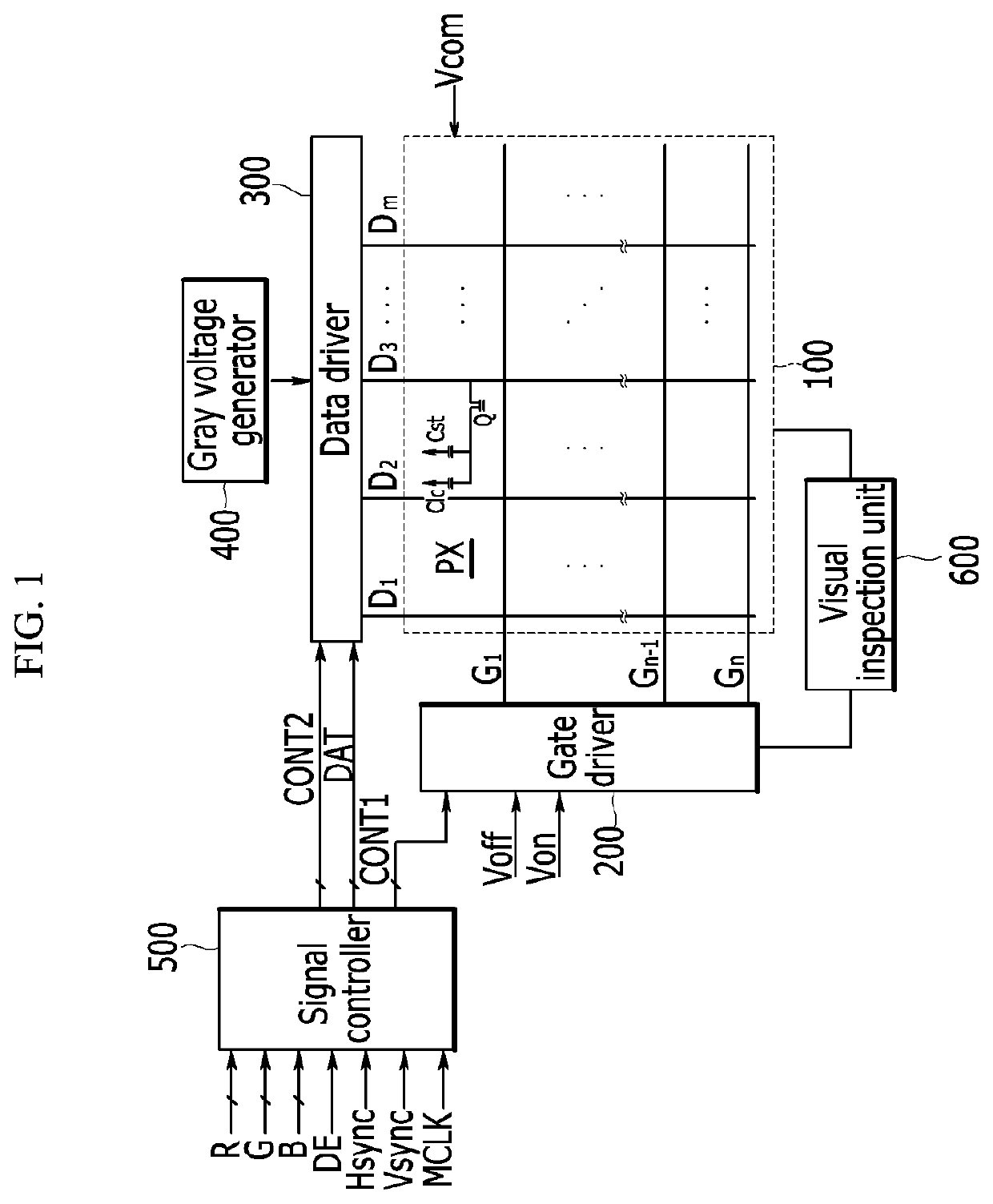
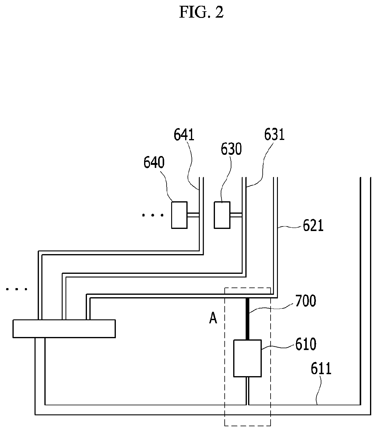
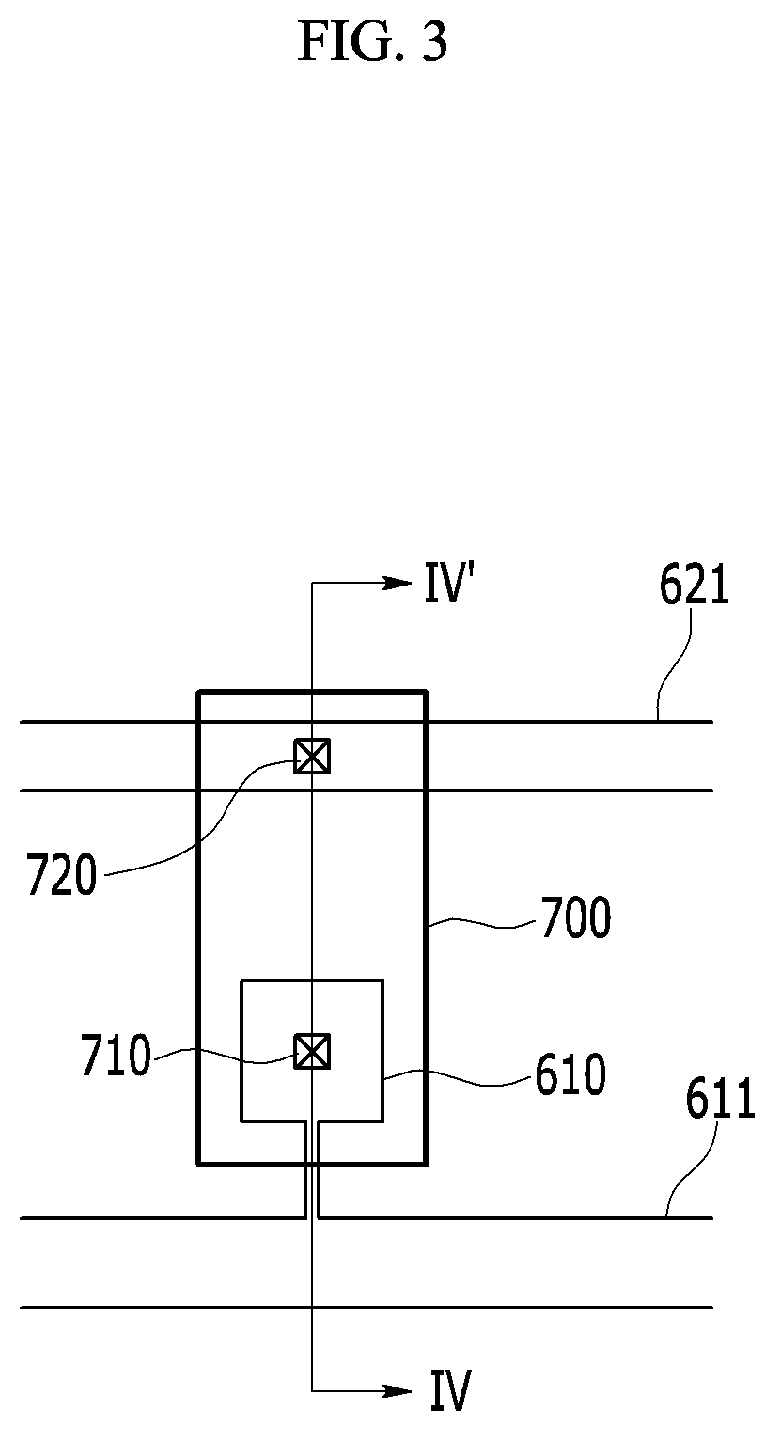
[0009]The present invention has been made in an effort to provide a liquid crystal display having advantages of reducing the number of pads for visual inspection of the liquid crystal display.
[0010]The present invention has been made in an effort to provide a liquid crystal display having advantages of reducing an inflow of static electricity occurring at the time of visual inspection.
[0011]The present invention has been made in an effort to provide a liquid crystal display having advantages of easily aligning a pad and a jig pin of the liquid crystal display at the time of visual inspection.
[0025]According to an exemplary embodiment of the present invention, it is possible to implement the liquid crystal display having the narrow bezel by reducing the size of the outside portion of the liquid crystal display. Further, it is possible to minimize the inflow of static electricity at the time the visual inspection is performed and easily align the pad and the jig pin for the visual inspection.

Problems solved by technology

However, in the case of the liquid crystal display to which the narrow bezel is applied, a space in which the test pad and the signal line are disposed may be insufficient.

Method used


Image

  • Liquid crystal display
  • Liquid crystal display
  • Liquid crystal display

Examples


Embodiment Construction

[0034]In the following detailed description, only certain exemplary embodiments of the present invention have been shown and described, simply by way of illustration. As those skilled in the art would realize, the described embodiments may be modified in various different ways, all without departing from the spirit or scope of the present invention. Accordingly, the drawings and description are to be regarded as illustrative in nature and not restrictive Like reference numerals designate like elements throughout the specification. In addition, the detailed description of the widely known technologies will be omitted.

[0035]It will be understood that when an element such as a layer, film, region, or substrate is referred to as being “on” another element, it can be directly on the other element or intervening elements may also be present. Further, in the specification, the word “on” means positioning on or below the object portion, but does not essentially mean positioning on the upper...


PUM

PropertyMeasurementUnit
areaaaaaaaaaaa
voltageaaaaaaaaaa
sizeaaaaaaaaaa

Abstract

A liquid crystal display, including: a liquid crystal panel; and a visual inspection unit positioned in an outer region of the liquid crystal panel and transferring a test signal to the liquid crystal panel, in which the visual inspection unit includes: a test pad to which a test signal is applied; a first test line connected to the test pad; and a second test line connected to the test pad through a bridge line.

Description

CLAIM OF PRIORITY[0001]This application makes reference to, incorporates the same herein, and claims all benefits accruing under 35 U.S.C. § 119 from an application earlier filed in the Korean Intellectual Property Office on the 6 of Jan. 2015 and there duly assigned Serial No. 10-2015-0001402.BACKGROUND OF THE INVENTION[0002]Field of the Invention[0003]A liquid crystal display is provided.[0004]Description of the Related Art[0005]Recently, as a liquid crystal display is implemented by a narrow bezel, a size of a signal wire and a pad at an outside portion of the liquid crystal display has been reduced. As a result, a bump end of a chip on glass (COG) is implemented as a fine pattern and visual inspection of the liquid crystal display is performed instead of a cell test which is the existing driving test method of the liquid crystal display.[0006]For the visual inspection, separate inspection lines connected to a gate line and a data line are installed on a thin film transistor subs...

Claims


Application Information

Patent Timeline
Patent Type & Authority Patents(United States)
IPC IPC(8): G02F1/13
CPCG02F1/1309G02F1/133388G02F1/136254G09G3/006
Inventor JEON, YOUNG JAEKWAK, YUN HEEKIM, HYOUNG-JOONCHOI, JAE HOKIM, KYUNG HYUNCHANG, JONG WOONG
Owner TCL CHINA STAR OPTOELECTRONICS TECH CO LTD
Why Eureka
Try Eureka