Rotor for rotating electric machine

a technology of rotating electric machines and rotating parts, which is applied in the direction of dynamo-electric machines, magnetic circuit rotating parts, magnetic circuit shape/form/construction, etc., can solve problems such as failure to achieve stress-induced failure, and achieve the effect of preventing stress concentration and high core member strength

Active Publication Date: 2020-01-14
DENSO CORP
View PDF10 Cites 0 Cited by
  • Summary
  • Abstract
  • Description
  • Claims
  • Application Information

AI Technical Summary

Benefits of technology

[0009]With the above configuration, the at least some of the soft-magnetic bodies are fixed to one another with residual stress at the at least one staking portion dispersed in the circumferential direction of the core member and thus without concentration of the residual stress in the core member. Moreover, during rotation of the rotor, the claw-shaped magnetic pole portions of the field core are deformed radially outward due to the centrifugal force, thereby inducing stress in the core member that covers the radially outer peripheries of the claw-shaped magnetic pole portions. However, since the at least some of the soft-magnetic bodies are fixed to one another by the at least one staking portion, the stress induced by the radially outward deformation of the claw-shaped magnetic pole portions can be transferred between the at least some of the soft-magnetic bodies. Consequently, it becomes possible to prevent concentration of the stress induced by the radially outward deformation of the claw-shaped magnetic pole portions from occurring in the core member and thereby ensure high strength of the core member.

Problems solved by technology

However, the inventor of the present application has found that the core member disclosed in the above patent document involves the following problems.
Since the core member has the protrusions and recesses formed on the radially outer surface thereof, stress concentration may occur at locations where the radial widths of the soft-magnetic sheets forming the core member are small, thereby causing a stress-induced failure to occur.

Method used


Image

  • Rotor for rotating electric machine
  • Rotor for rotating electric machine
  • Rotor for rotating electric machine

Examples


first modification

[First Modification]

[0077]In this modification, as shown in FIG. 9, in the core member 35, there are formed four staking portions 37 at a constant pitch in the circumferential direction of the core member 35, unlike in the above-described embodiment. In addition, in this modification, the number of the claw-shaped magnetic pole portions 323 of the field core 32 (i.e., the number of the first and second claw-shaped magnetic pole portions 323a and 323b of the first and second pole cores 32a and 32b) is equal to 16. That is, the number of the staking portions 37 arranged in the circumferential direction of the core member 35 is different from the number of the claw-shaped magnetic pole portions 323 of the field core 32, as in the above-described embodiment.

second modification

[Second Modification]

[0078]In this modification, as shown in FIG. 10, the number of the staking portions 37 arranged in the circumferential direction of the core member 35 is set to a prime number, more particularly to 5.

[0079]Setting the number of the staking portions 37 to a prime number, no constant-loop eddy current is generated in the core member 35. Consequently, it is possible to reduce the eddy current loss in the core member 35.

[0080]While the above particular embodiment and modifications have been shown and described, it will be understood by those skilled in the art that various further modifications, changes, and improvements may be made without departing from the spirit of the present invention.

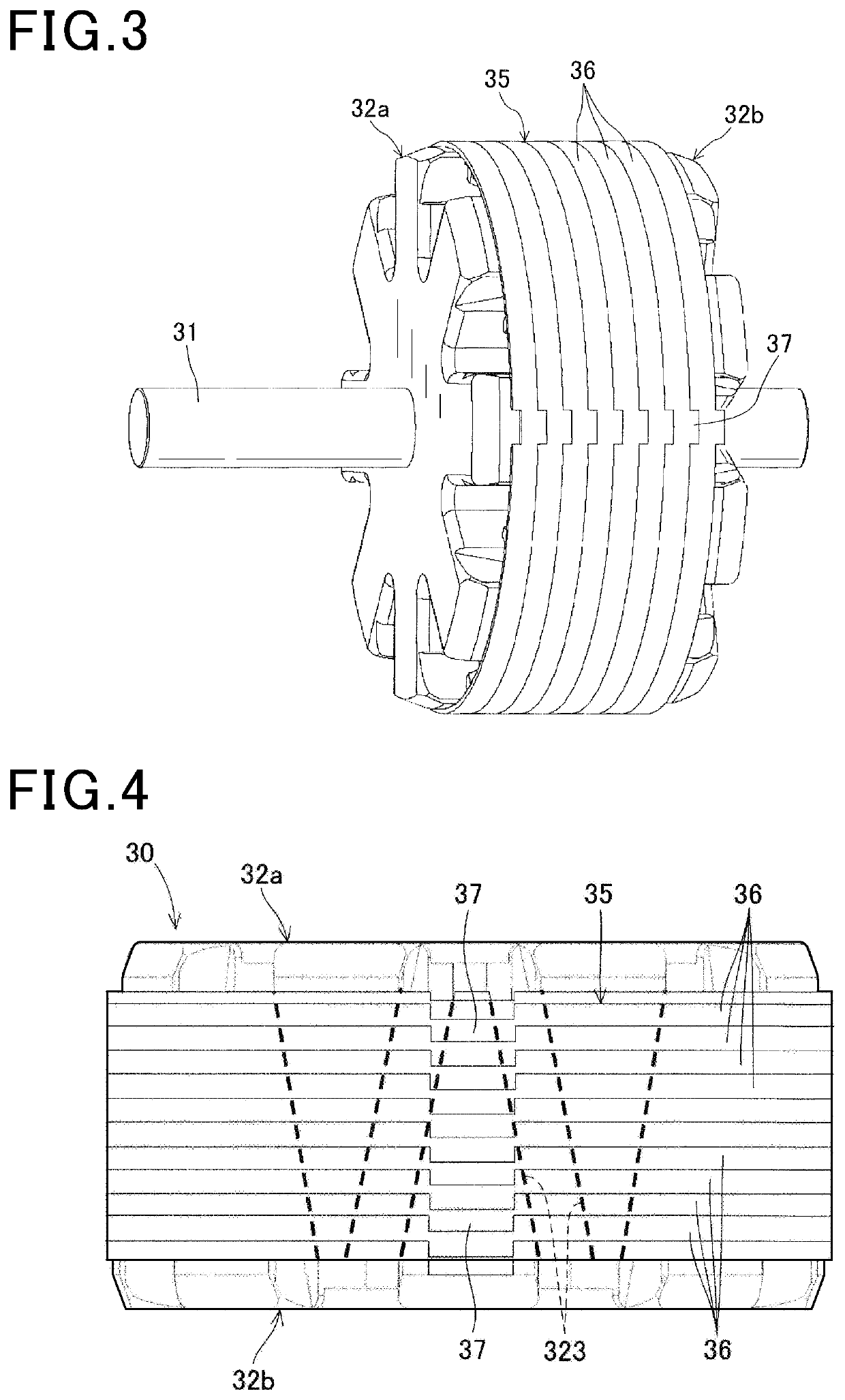
[0081]For example, in the above-described embodiment, each of the staking portions 37 is formed over all of the steel sheets 36 forming the core member 35. However, each of the staking portions 37 may be formed over only some of the steel sheets 36.

[0082]In the above-described em...


PUM


Abstract

A rotor for a rotating electric machine includes a field core having a plurality of claw-shaped magnetic pole portions, a field coil wound on the field core, and a hollow cylindrical core member disposed to cover radially outer peripheries of the claw-shaped magnetic pole portions of the field core. The core member is formed of a plurality of soft-magnetic bodies that are laminated in an axial direction of the core member. At least some of the soft-magnetic bodies forming the core member are fixed to one another by at least one staking portion that is formed along the axial direction of the core member.

Description

CROSS-REFERENCE TO RELATED APPLICATION[0001]This application is based on and claims priority from Japanese Patent Application No. 2016-112258, filed on Jun. 3, 2016, the content of which is hereby incorporated by reference in its entirety into this application.BACKGROUND1 Technical Field[0002]The present invention relates to rotors for rotating electric machines that are used in, for example, motor vehicles as electric motors and electric generators.2 Description of Related Art[0003]There are known rotating electric machines which include a stator having a stator coil wound on a stator core and a rotor that is rotatably disposed so as to radially face the stator through an electromagnetic gap formed therebetween.[0004]Moreover, there are also known Lundell-type rotors which include a field core and a field coil. The field core has a cylindrical boss portion fixed on a rotating shaft and a plurality of claw-shaped magnetic pole portions located radially outward of the boss portion. I...

Claims


Application Information

Patent Timeline
Patent Type & Authority Patents(United States)
IPC IPC(8): H02K1/24H02K1/27H02K21/04
CPCH02K21/044H02K1/243H02K1/27
Inventor TAKAHASHI, YUKI
Owner DENSO CORP
Why Eureka
Try Eureka