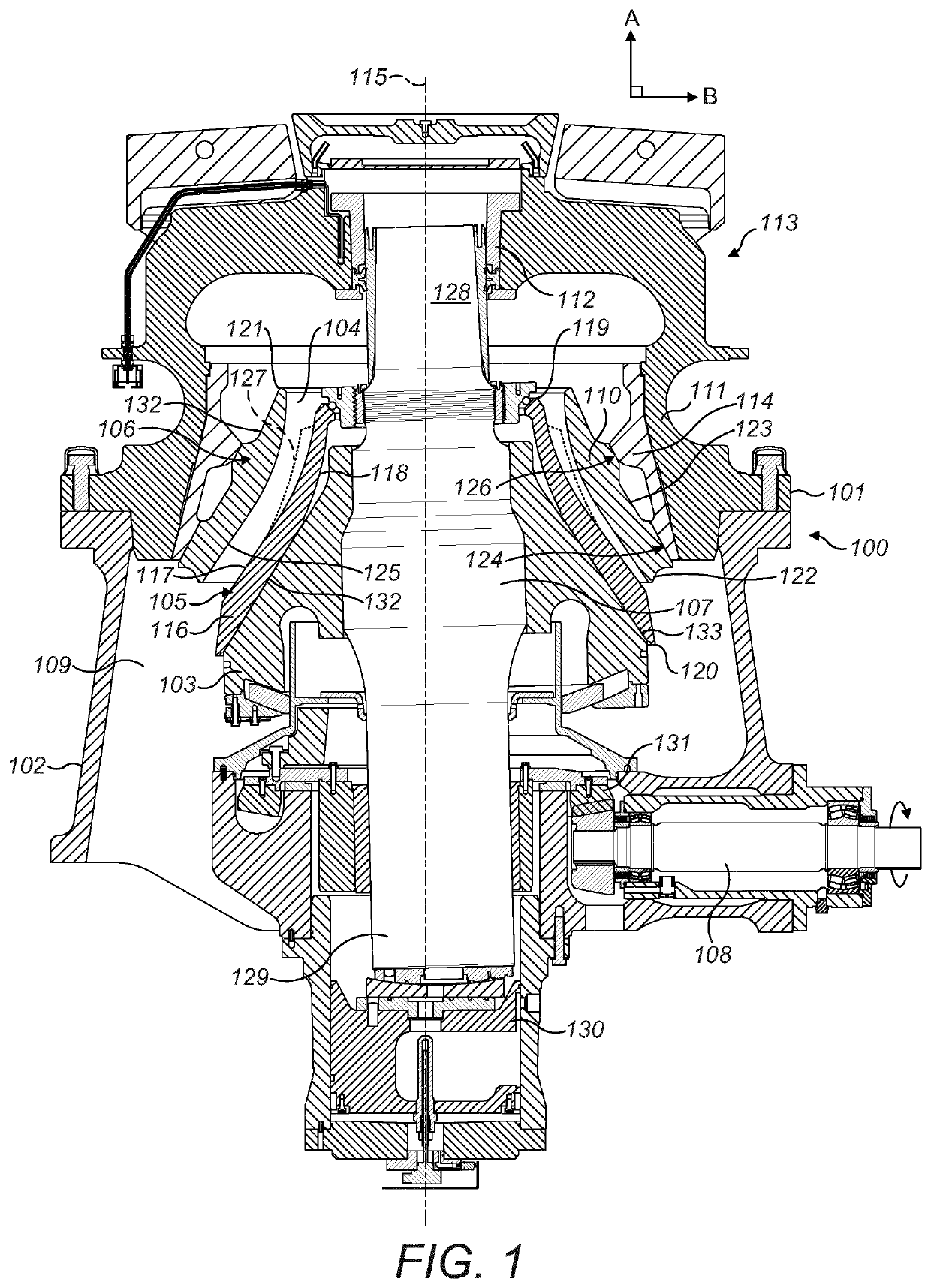
[0007]It is an objective of the present invention to provide a gyratory crusher and at least one crushing shell being optimised to control the choke zones within the crushing chamber and to provide a crusher having a balanced capacity with increased reduction potential. It is a further objective to provide a gyratory crusher to control the flow of material passing through the crushing zone to allow the crusher to be operated at reduced close side setting (CSS) without increasing the crushing force. It is a further objective of the present invention to increase and optimise the crushing capacity of the entire crushing process particularly where a gyratory crusher is operated in a closed crushing circuit (being coupled to a downstream screen) by generating consistently crushed material having a particle or piece size within a predetermined reduction range.
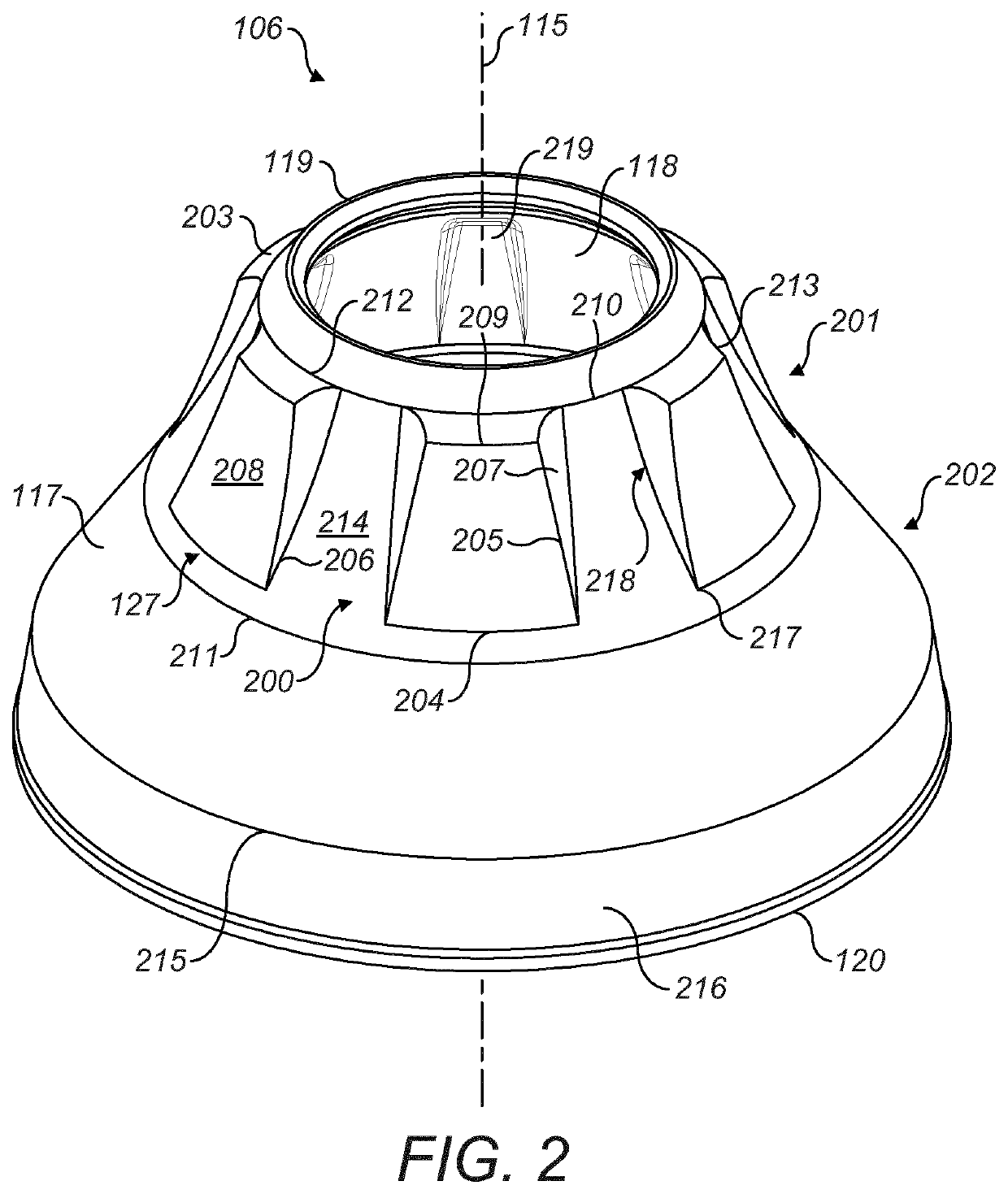
[0009]The wedges are positioned at an axially upper region of the shell so as to extend axially downward along the body of the shell and to decrease in radial extension in the axially downward direction such that the wedges do not continue to the axially lower regions of the crushing surface. Accordingly, the wedges are intended to control the flow of material into the axially lower crushing zones between the inner and outer crushing shells. The wedges effectively decrease the overall volume within a ‘choke zone’ and this serves to raise the position of the choke zone axially upward in the crushing chamber. The wedges are further advantageous to reduce the amount of material being processed in the crushing chamber and to allow the crusher to be operated at a smaller CSS without a requirement to increase the crushing force. Accordingly, the reduction level of the crusher is increased together with the process capacity as the need to ‘open’ the crushing zone (typically via hydraulic rams) is avoided as the crusher does not experience choking as with conventional crushers.
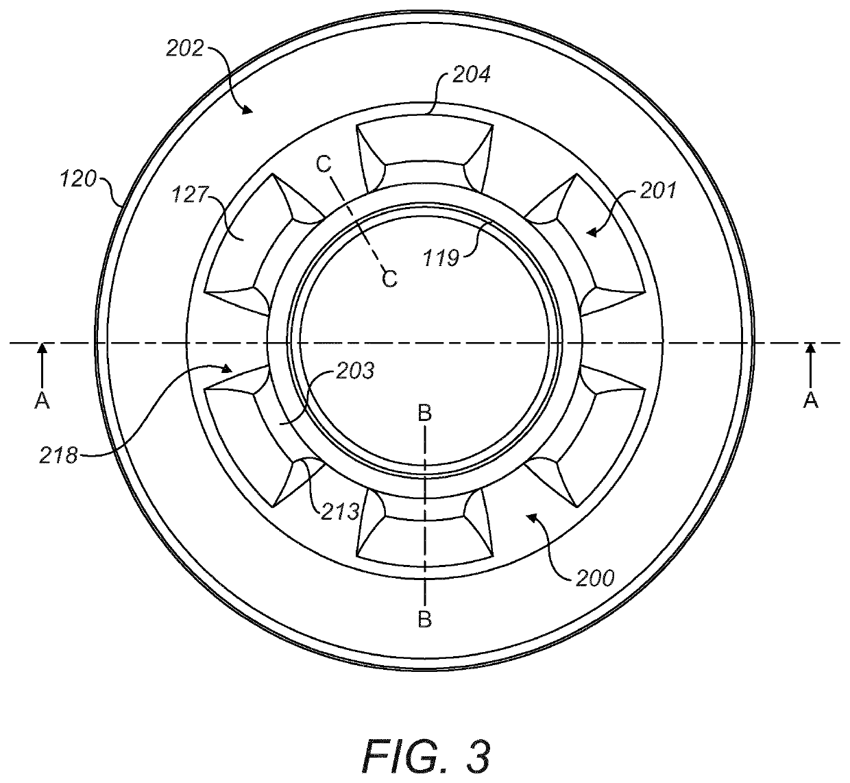
[0011]Accordingly, the radial distance of the crushing surface relative to a central axis of the shell increases and decreases according to an alternating profile in a circumferential direction around the axis at an axial position of the wedges and channels. The circumferentially extending alternating profile of the crushing surface at the axially upper region of the shell is effective to control the volume of material that is fed to be axially lower crushing region (between the opposed inner and outer crushing shells). That is, the radially extended shell walls at the region of the wedges feed material into the channels to effectively raise axially the choke point of the crushing zone. This is advantageous to avoid undesirable and premature choking of the crusher. The decreased area function (due to the presence of the wedges) within the crushing zone is effective to allow for a greater reduction whilst maintaining and optimising the particle size distribution exiting the crusher. Accordingly, the need to ‘open’ the crushing zone to purge the crusher is avoided.
[0013]Optionally, each of the wedges may comprise a radial thickness that decreases in a direction from the first end to the second end. Optionally, the shell wall may comprise a radial thickness that decreases at a region of each wedge in the axial direction from the region of the first end to the second end. Preferably, the shell wall comprises a radial thickness that is substantially uniform at the region of each wedge in the axial direction from the region of the first end to the second end. This is advantageous to provide a uniform cooling rate at the shell wall which in turn eliminates or reduces porosity of the cast material. Preferably, a radial distance between the crushing surface of each wedge and the crushing surface of each channel decreases in an axially downward direction from the region of the first end to the second end.
[0014]Preferably, each of the wedges comprise a tapered shape profile in the axial direction such that a radial extension of the wall at a region of each wedge is greater at an axially upper region of each wedge than an axially lower region of each wedge relative to the central axis. This reducing tapered radial extension of the wedge from the central axis (and importantly each neighbouring channel) provides a smooth transition for material flowing from the axially upper to the axially lower crushing zones. Optionally, the crushing surface at the region of each wedge comprises a concave shape profile in the axial direction. That is, the effective difference in the radial extension of the wedge crushing surface relative to the radial position of the crushing surface at each channel decreases to zero so as to provide a smooth transition onto the axially lower crushing surface.
[0017]According to the preferred embodiment, the shoulders (end surfaces) of each wedge, that define each channel, are substantially uniform in shape and configuration such that each lengthwise edge of each wedge, and therefore each channel, is substantially identical. In particular, the tapered profile of each side surface of each wedge, at each side of each wedge, is substantially the same or identical. Accordingly, each channel is defined and bordered by a side surface of each wedge that is substantially the same or identical. Preferably, each shoulder comprises a pair of axially extending lengthwise side surfaces, each side surface having a tapered shape profile in the circumferential direction to provide a smooth transition with a respective channel. The tapered shape profile of the lengthwise side surfaces of each wedge is configured to provide a smooth transition for material flow from the surface of the wedge into the intermediate channel for the subsequent controlled feed to the lower crushing zone. Preferably, the sides (or shoulders) of the wedges are also tapered in the axial direction so as to decrease to zero at approximately the mid-region between the upper and lower ends of the shell.


