Failure detection apparatus for voltage sensor

a voltage sensor and failure detection technology, applied in the direction of voltage measurement only, instruments, measurement devices, etc., can solve the problems of accelerating the deterioration of the battery, and achieve the effect of reliably detecting failures in voltage sensors

Active Publication Date: 2020-02-04
MITSUBISHI ELECTRIC CORP
View PDF22 Cites 3 Cited by
  • Summary
  • Abstract
  • Description
  • Claims
  • Application Information

AI Technical Summary

Benefits of technology

[0019]According to the present invention, it becomes possible to obtain a failure detection apparatus for voltage sensor capable of reliably detecting failure in a voltage sensor for detecting battery voltage, without erroneous determination.

Problems solved by technology

If such a secondary battery is over-charged or over-discharged, deterioration in the battery is accelerated.
However, in the above detection means, if the voltage sensor has failed, charging or discharging is performed based on an erroneous SOC, and therefore the SOC of the secondary battery may become an over-charged state or over-discharged state.

Method used


Image

  • Failure detection apparatus for voltage sensor
  • Failure detection apparatus for voltage sensor
  • Failure detection apparatus for voltage sensor

Examples


embodiment 1

[0028

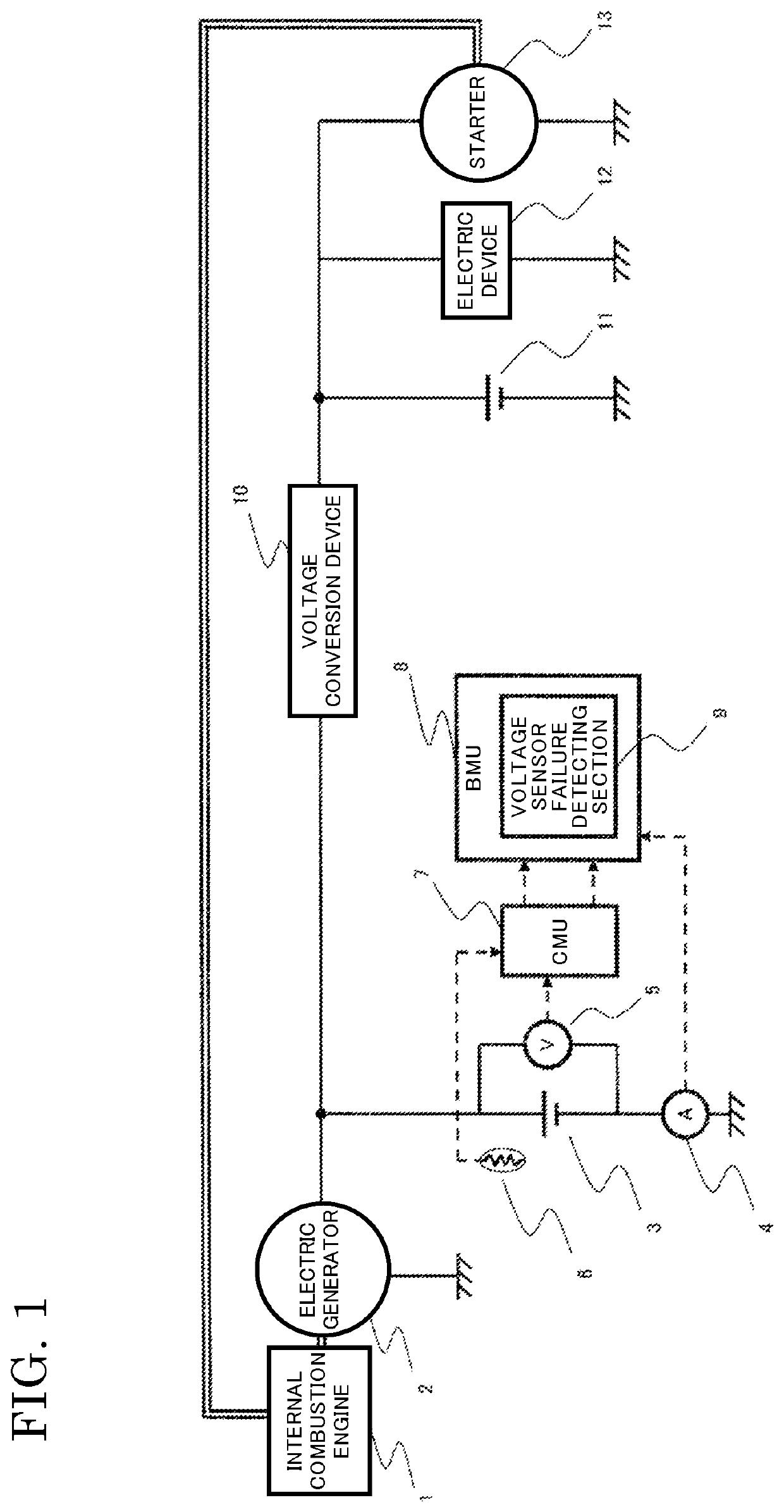
[0029]FIG. 1 shows an example of a schematic configuration diagram of a power supply system for an internal combustion engine, provided with a failure determination apparatus according to the present invention.

[0030]An internal combustion engine 1 and an electric generator 2 are connected via a belt or the like, so that when the internal combustion engine 1 rotates, the electric generator 2 also rotates.

[0031]When the electric generator 2 rotates, the electric generator 2 performs electric generation. The generated electric energy is used to charge a battery 3, is consumed by an electric device 12 after undergoing voltage conversion by a voltage conversion device 10, or is used to charge a sub battery 11.

[0032]Power for driving a starter 13 for starting the internal combustion engine 1 is supplied from the sub battery 11. The batteries are a lithium ion battery, etc.

[0033]Here, the voltage conversion device 10 is provided under the assumption that voltages of the battery3 and t...

embodiment 2

[0052

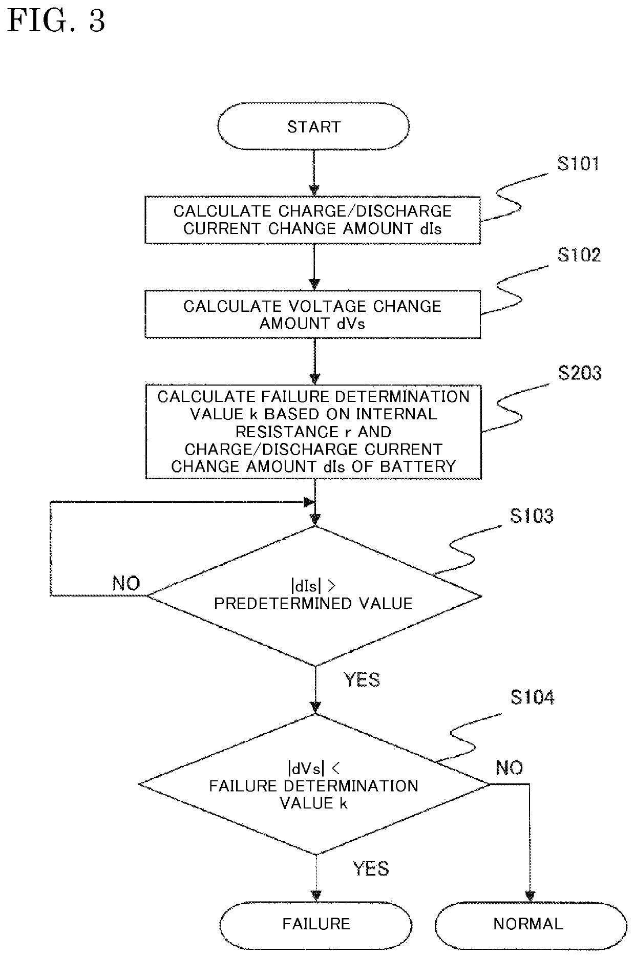
[0053]FIG. 3 is a flowchart showing a process by a failure detection apparatus for the voltage sensor 5 according to embodiment 2 of the present invention. The process is executed periodically (for example, every 10 ms).

[0054]Embodiment 2 is different from embodiment 1 in the following.

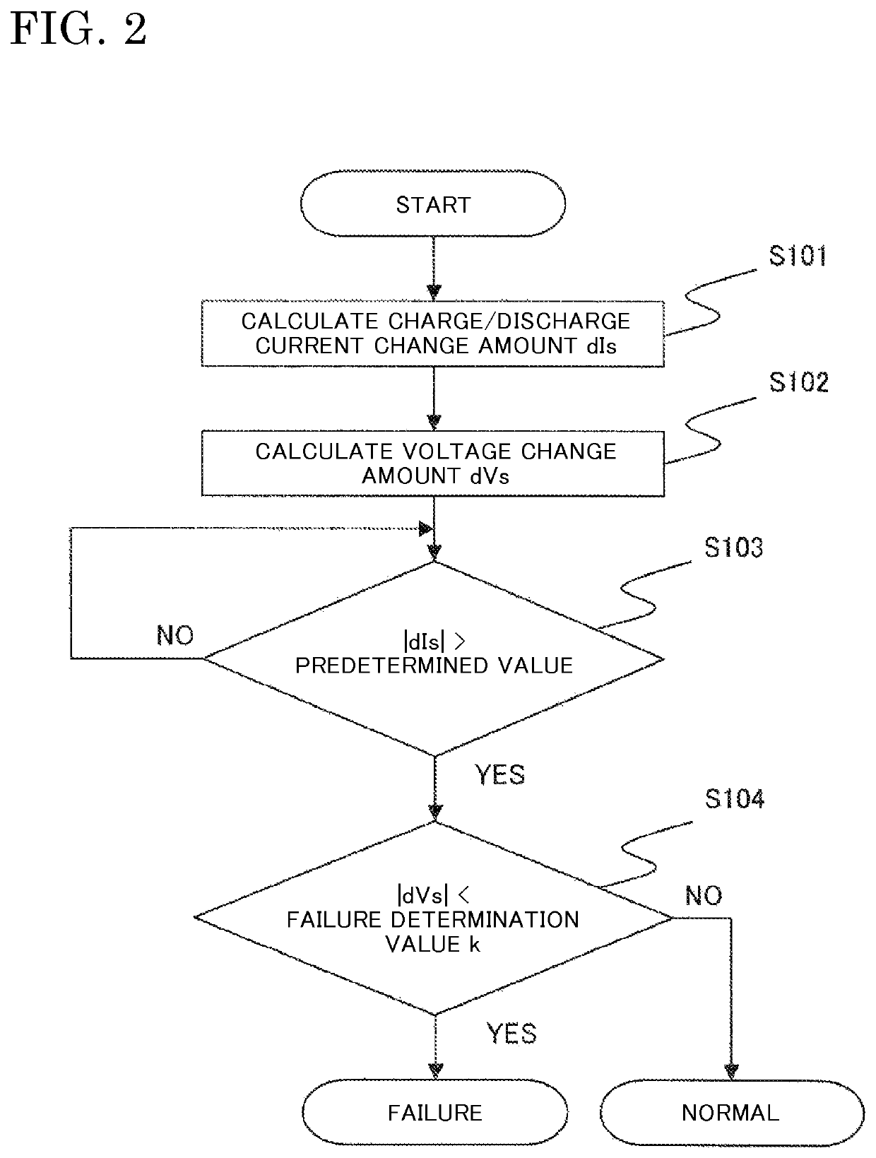
[0055]That is, in FIG. 3, step 5203 is added as compared to FIG. 2.

[0056]Hereinafter, a difference in FIG. 3 from FIG. 2 will be described.

[0057]The battery voltage V in charging or discharging is represented by the following expression (1) as described above.

V=E+r·I  (1)

[0058]If the charge / discharge current I changes, the battery voltage V changes by an amount corresponding to a product of the internal resistance r and the charge / discharge current change amount dIs, i.e., r·dIs.

[0059]The internal resistance r of the battery 3 varies depending on the type of the battery 3, for example.

[0060]Therefore, even if the charge / discharge current change amount dIs is the same, if the internal resistance r...

embodiment 3

[0063

[0064]FIG. 4 is a flowchart showing a process by a failure detection apparatus for the voltage sensor 5 according to embodiment 3 of the present invention. The process is executed periodically (for example, every 10 ms).

[0065]Embodiment 3 is different from embodiment 2 in the following.

[0066]That is, in FIG. 4, step S303 is added as compared to FIG. 3.

[0067]Hereinafter, a difference in FIG. 4 from FIG. 3 will be described.

[0068]The internal resistance r of the battery 3 indicates a value different depending on a temperature T of the battery 3, the state of charge SOC of the battery 3, or a deterioration degree of the battery 3.

[0069]In step S303, considering that the internal resistance varies depending on the temperature, the state of charge, or the deterioration degree of the battery 3, the internal resistance r of the battery 3 is calculated based on a map of the internal resistance r with respect to the battery temperature T detected by the temperature sensor 6, the state o...


PUM


Abstract

A method and apparatus to reliably detect failure in a voltage sensor which detects battery voltage, without erroneous determination, is provided. A current sensor detects charge / discharge current of a battery. The method comprises calculating a charge / discharge current change amount based on the current detected by the current sensor. A voltage sensor detects voltage of the battery. The method also comprises calculating a voltage change amount based on the voltage detected by the voltage sensor. If the charge / discharge current change amount is equal to or greater than a predetermined value and the voltage change amount is smaller than a failure determination value, it is determined that the voltage sensor has failed.

Description

CROSS REFERENCE TO RELATED APPLICATIONS[0001]This application is a National Stage of International Application No. PCT / JP2013 / 060678 filed Apr. 9, 2013, the contents of all of which are incorporated herein by reference in their entirety.TECHNICAL FIELD[0002]The present invention relates to a failure detection apparatus for detecting failure in a voltage sensor, particularly, a voltage sensor for detecting battery voltage of a secondary battery.BACKGROUND ART[0003]A vehicle is provided with a secondary battery that temporarily stores electric energy generated by an electric generator connected to an internal combustion engine via a belt or the like, for supplying required power to electric devices even when the internal combustion engine is not rotating and power cannot be generated by the electric generator, for example.[0004]If such a secondary battery is over-charged or over-discharged, deterioration in the battery is accelerated. Therefore, in the case of using a secondary batter...

Claims


Application Information

Patent Timeline
Patent Type & Authority Patents(United States)
IPC IPC(8): G01R35/00G01R31/36G01R19/165G01R31/389
CPCG01R31/3648G01R19/16528G01R35/00G01R31/389G01R19/0084G01R31/3842
Inventor NISHIJIMA, YOSHIMASAYAMAGUCHI, SHINGOWACHI, SATOSHI
Owner MITSUBISHI ELECTRIC CORP
Why Eureka
Try Eureka