
Steering Column Assembly Comprising A Steering Column The Tilt And Length Of Which Can Be Modified

a technology of steering column and assembly, which is applied in the direction of steering column, steering parts, vehicle components, etc., can solve the problems of affecting affecting the stability of the hoop relative to the bracket, and affecting the stability of the hoop, etc., so as to improve the safety of vehicle occupants, maintain comfort functions, and ensure the effect of stability

Inactive Publication Date: 2007-11-29
DAIMLER AG
View PDF16 Cites 4 Cited by
  • Summary
  • Abstract
  • Description
  • Claims
  • Application Information

AI Technical Summary

Benefits of technology

[0004] Example embodiments of the present invention may provide a steering column arrangement, in which the safety of vehicle occupants may be increased and reliable use of the steering column arrangement may be ensured while maintaining comfort functions.
[0005] According to example embodiments of the present invention, a steering column arrangement includes a bracket which is arranged fixedly on the vehicle, and the steering column is configured so as to be adjustable in its inclination and length for reasons of comfort. In order to fix the steering column in its position, clamping device(s) are additionally provided. In order to increase the safety of vehicle occupants in the case of a crash, a bracket slide is arranged between the bracket which is arranged fixedly on the vehicle and the steering column having the clamping device(s), which bracket slide is connected to the bracket such that a linear displacement of the bracket slide is possible along the bracket. A locking device is provided between the bracket slide and the bracket. The locking device makes it possible that the steering column arrangement may be locked in a predefined position with respect to the bracket. It is possible that the predefined position of the steering column is the position which the steering column assumes during normal use.
[0006] According to an exemplary embodiment, the locking device may be released if a force which is applied to the steering column in the axial direction is exceeded, as a result of which it is possible for the bracket slide with the steering column and the clamping device to be displaced relative to the bracket. It is possible that the predefined amount of force is oriented toward a crash force, so that, for example, in the case of a crash if a force which acts in the axial direction is applied to the steering column, the steering column is displaced at exactly that instant, at which possible loads on the occupant have become excessively great. In this manner, it may be possible to increase the safety of vehicle occupants.
[0009] The tear-off pin may have a constriction which extends around the radial circumference of the tear-off pin. The constriction may be a groove or a chamfer. The constriction may be arranged, for example, in the center of the tear-off pin. The tear-off pin has a defined diameter at the level of the constriction. This contributes to the tear-off pin failing at a precisely predictable force, with the result that the force may be set precisely, above which the steering column is displaced relative to the bracket. This plays a role, for example, when consideration is taken that the holes in the bracket slide and the sleeve which accommodate the tear-off pin may be subject to tolerances, with the result that, when the tear-off pin is introduced, it would acquire a different diameter without the constriction, depending on the tolerance of the hole. However, a different diameter has the consequence of different tear-off forces and thus different displacement instants of the steering column relative to the bracket.
[0010] The constriction may be arranged at the level of the tear-off pin, which level corresponds to a dividing plane between the bracket slide and the sleeve in the installed state. If the constriction is arranged at the level of this dividing plane, the crash force is directed directly at the correct point of the tear-off pin in a crash and reliable failure of the tear-off pin may be ensured.
[0012] It is possible for a gap which exists between the receptacle and the sleeve to be filled with plastic by injection molding. This feature serves to produce a playfree connection between the bracket slide and the sleeve, in order that no undesirable relative movements and any possible noise associated with the latter may occur during use of the steering column. The filling operation by injection molding may be performed after the assembly of the steering column arrangement, with the result that a play which is initially present between the bracket slide and the sleeve may be used to compensate for assembly tolerances.

Problems solved by technology

The clamping devices are designed such that they block the capability of changing the position of the steering column reliably and permanently.
Secondly, the clamping devices have to be designed such that they permit a change in the position of the steering column simply when required.
However, it is not apparent how the hoop is fixed relative to the bracket during normal use of the steering column arrangement.
It is possible that the predefined amount of force is oriented toward a crash force, so that, for example, in the case of a crash if a force which acts in the axial direction is applied to the steering column, the steering column is displaced at exactly that instant, at which possible loads on the occupant have become excessively great.
This contributes to the tear-off pin failing at a precisely predictable force, with the result that the force may be set precisely, above which the steering column is displaced relative to the bracket.
However, a different diameter has the consequence of different tear-off forces and thus different displacement instants of the steering column relative to the bracket.

Method used


Image

  • Steering Column Assembly Comprising A Steering Column The Tilt And Length Of Which Can Be Modified
  • Steering Column Assembly Comprising A Steering Column The Tilt And Length Of Which Can Be Modified
  • Steering Column Assembly Comprising A Steering Column The Tilt And Length Of Which Can Be Modified

Examples


Embodiment Construction

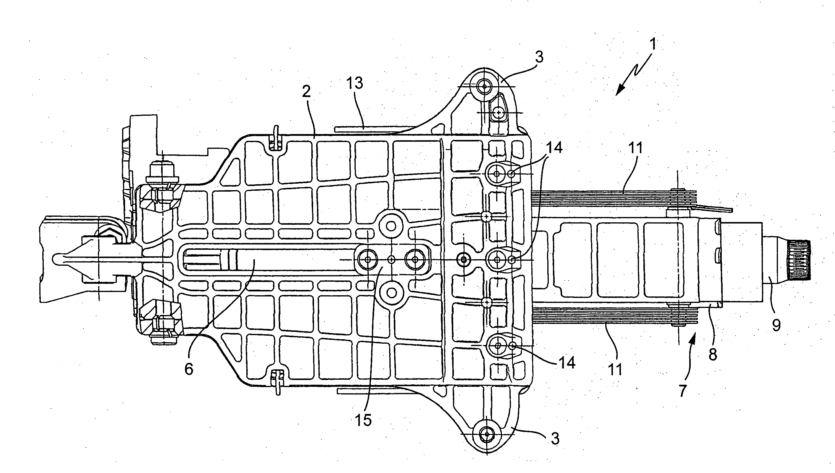
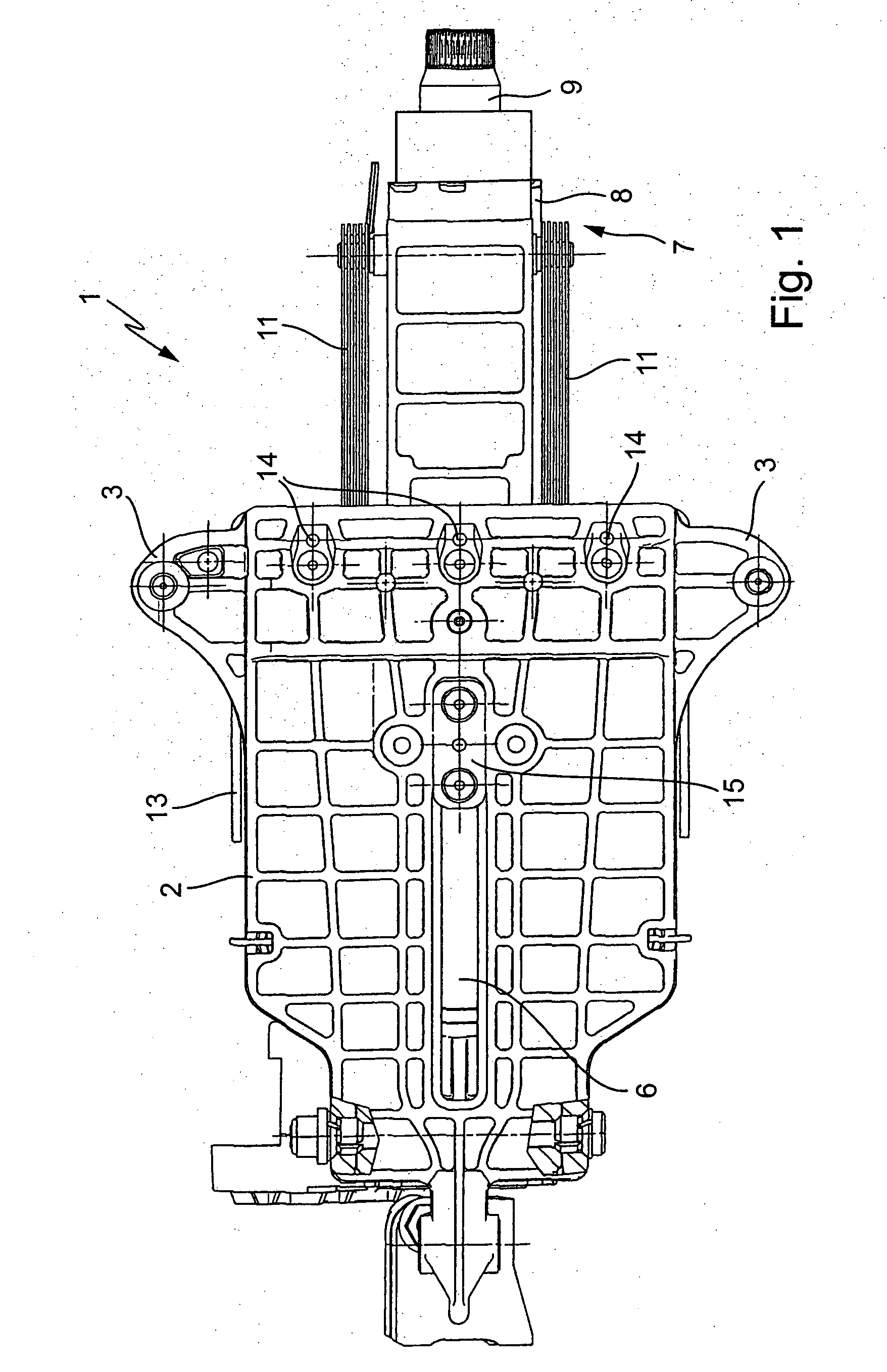
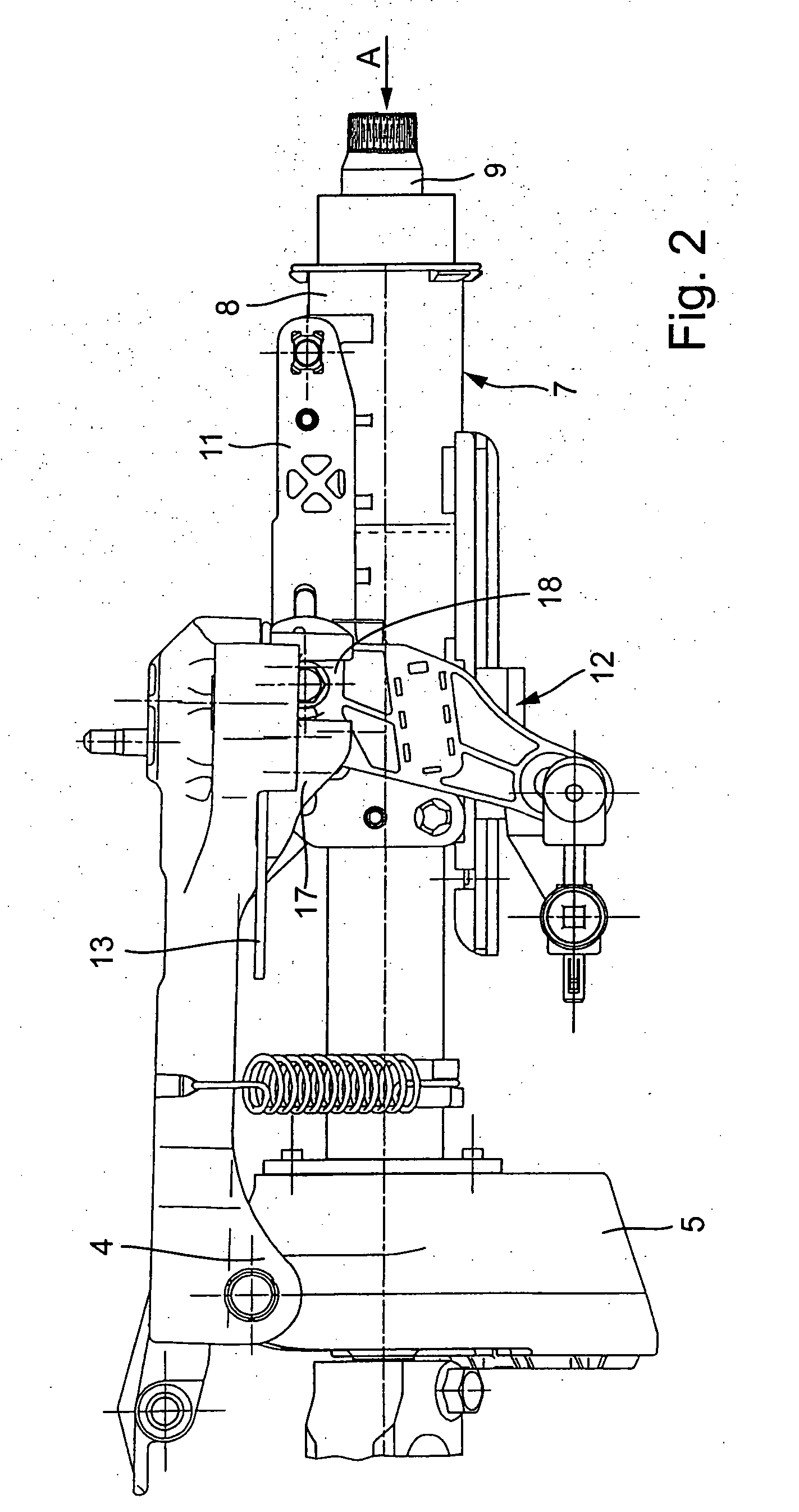
[0022]FIG. 1 illustrates a steering column arrangement 1. The steering column arrangement 1 has a bracket 2. The bracket 2 has a substantially rectangular cross-section. It has receptacles 3 for fastening devices. The bracket 2 is mounted via the fastening devices on a vehicle. Furthermore, receptacles 4 are provided (cf., FIG. 2) which serve to accommodate a further fastening element. The fastening element which is arranged in the receptacle 4 serves to fasten a sleeve 5. Furthermore, the bracket 2 has a slot 6 which extends over a large part of the length of the bracket 2. The function of the slot 6 will be explained in greater detail in the following text.

[0023] Furthermore, the steering column arrangement 1 has a steering column 7 with a casing tube 8 and a steering column 9 which is mounted rotatably in the casing tube 8. The steering column 9 serves for holding a steering wheel and for transmitting a rotational movement which is imparted to the steering wheel by a driver to a...


PUM


Abstract

In a steering column arrangement having a bracket which is arranged fixedly on the vehicle, a steering column which has a casing tube and a steering spindle which is mounted rotatably therein, the steering column is configured so as to be adjustable in its inclination and length, and clamping device(s) are provided for fixing the steering column. In order to configure the steering column to be safer while maintaining comfort functions, the steering column is connected with the clamping device(s) to the bracket via a bracket slide which is mounted displaceably on the bracket, and locking device(s) being provided between the bracket slide and the bracket.

Description

FIELD OF THE INVENTION [0001] The present invention relates to a steering column arrangement. BACKGROUND INFORMATION [0002] In modern vehicle engineering, steering columns are configured such that their inclination and length can be changed for reasons of comfort. As a result, they can be adjusted to the individual requirements of a driver. Clamping devices are provided for fixing the steering column in its position. The clamping devices are designed such that they block the capability of changing the position of the steering column reliably and permanently. This is true, in particular, for the case in which a force which acts in the axial direction acts on the steering column, such as in the event of an accident. Secondly, the clamping devices have to be designed such that they permit a change in the position of the steering column simply when required. A steering column of this type is described, for example, European Published Patent Application No. 0 802 104. The steering column...

Claims


Application Information

Patent Timeline
Patent Type & Authority Applications(United States)
IPC IPC(8): B62D1/18B62D1/19
CPCB62D1/195
Inventor EGGERS, FREDERANG, MARCELHARMS, TORSTENKITTLER, HOLGERSAGNER, SVEN
Owner DAIMLER AG
Learn More