Tubular pin control system

a control system and tubular pin technology, applied in the direction of drilling rods, drilling pipes, drilling casings, etc., can solve the problems of affecting the operation of drilling operation, affecting the safety of the operation, and adding additional costs and labor

Active Publication Date: 2020-02-11
FORUM US
View PDF30 Cites 1 Cited by
  • Summary
  • Abstract
  • Description
  • Claims
  • Application Information

AI Technical Summary

Problems solved by technology

Sliding of the pin connection along the trough may damage the threads of the pin connection.
However, the protectors add additional costs and labor to the drilling operation when used.

Method used


Image

  • Tubular pin control system
  • Tubular pin control system
  • Tubular pin control system

Examples


Embodiment Construction

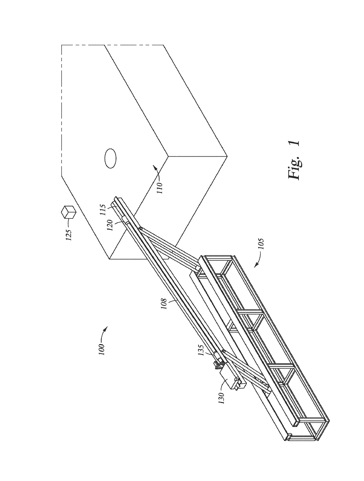
[0018]FIG. 1 is a schematic perspective view of a catwalk 105 next to a drill rig 100. The catwalk 105 is configured to convey a tubular 108 to and from a drill floor 110. The catwalk 105 includes a trough 115 along which the tubular 108 is conveyed to and from the drill floor 110. The tubular 108 has a box end 120 that may be coupled to an elevator 125, or other lift device, and raised or lowered to or from the drill floor 110. A skate 130 may engage a pin end 135 of the tubular 108. The skate 130 is powered to run along a length of the trough 115 of the catwalk 105 and may also be utilized to push or pull the tubular 108 during transfer of the tubular 108.

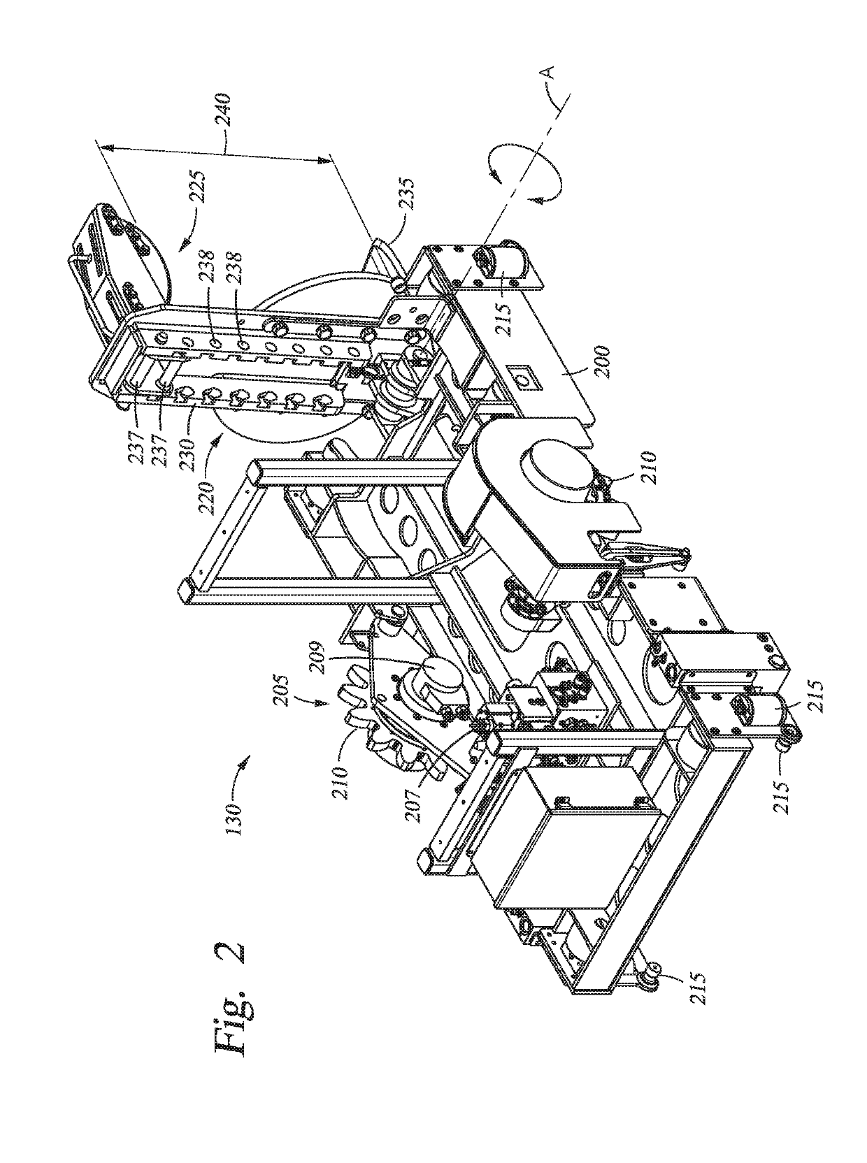
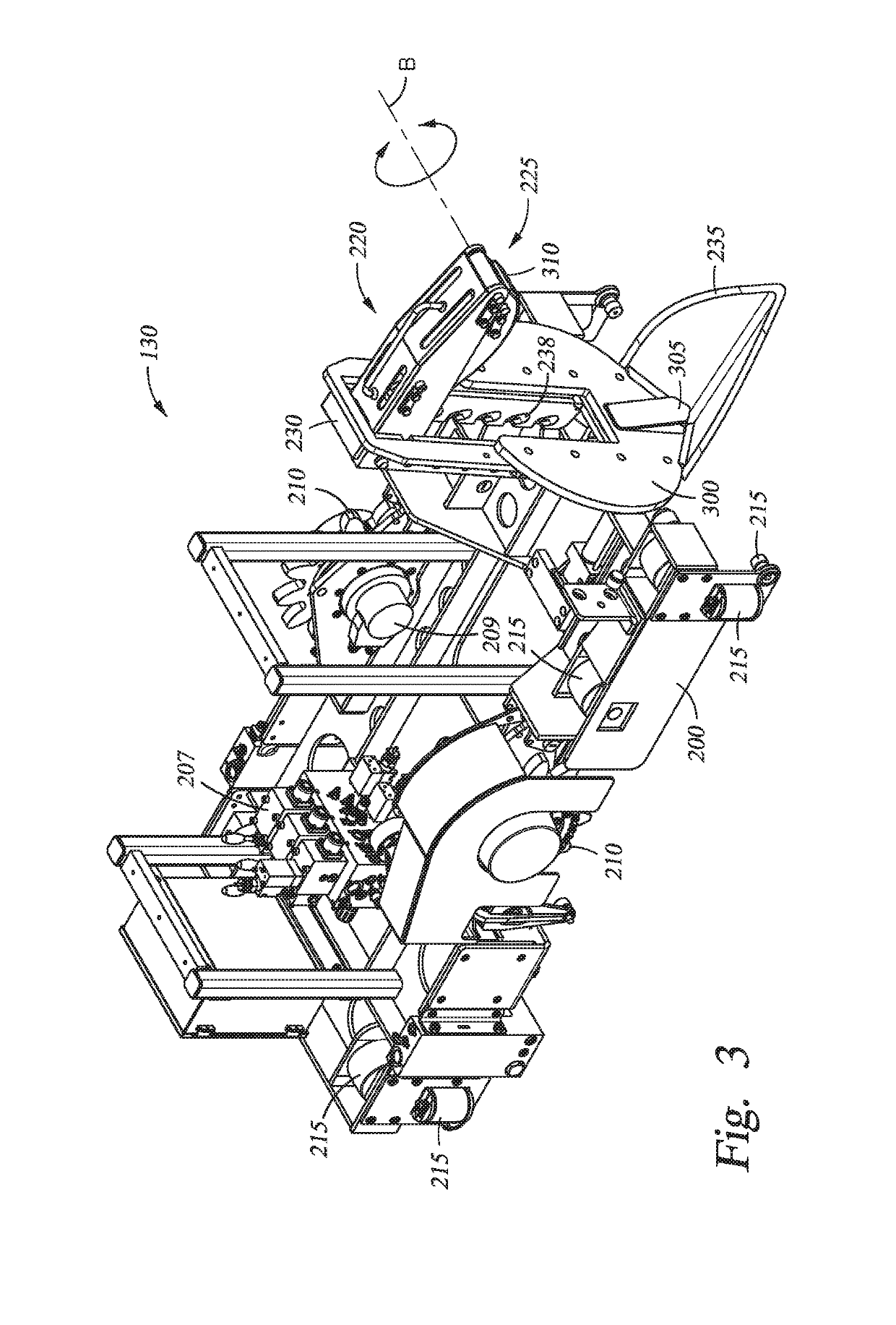
[0019]FIGS. 2 and 3 are isometric views of one embodiment of a skate 130 that may be used with the catwalk 105 of FIG. 1. The skate 130 includes a frame 200 having a drive system 205 that powers the skate 130 along the length of the trough 115 of FIG. 1. The drive system 205 in this embodiment includes a rack and pinion system, f...


PUM


Abstract

In one embodiment, a skate configured to engage a tubular while moving along a catwalk trough is provided. The skate comprises a frame having a drive system configured to move the tubular along the catwalk trough, a grip device coupled to the frame and configured to grip a pin end of the tubular, and a controller in communication with the drive system that controls movement of the frame based on movement of a box end of the tubular.

Description

CROSS-REFERENCE TO RELATED APPLICATION[0001]This application claims benefit of U.S. Provisional Patent Application Ser. No. 62 / 126,318, filed Feb. 27, 2015, which is hereby incorporated by reference herein.BACKGROUND[0002]Field[0003]Embodiments disclosed herein generally relate to catwalks for conveying tubulars between a drill floor and a lower level of a drilling rig or drill site. Specifically, embodiments disclosed herein relate to a system and method for moving tubulars along the catwalk.[0004]Description of the Related Art[0005]In a drilling operation or rig work-over operation, whether on a water-based (offshore) or a land-based drilling rig, tubulars, such as drill pipe, risers, casing or other tubulars, are often stored at, or supplied from, a level that is below the drill floor. The tubulars must be transported to the drill floor from a storage location at the lower level and then may be transported back to the storage location from the drill floor. The tubulars may be tra...

Claims


Application Information

Patent Timeline
Patent Type & Authority Patents(United States)
IPC IPC(8): E21B19/15
CPCE21B19/155E21B19/15
Inventor ARBELAEZ, JUANMEUTH, JOSHUA BRANDONBRYANT, AARON
Owner FORUM US
Why Eureka
Try Eureka