Ice skate blade measuring apparatus

a technology of measuring apparatus and blades, which is applied in the direction of instruments, skates, skating parts, etc., can solve the problems of bending in the blade section, little predictability in the process, and hesitant skaters to skate on the blade bent, etc., and achieve the effect of distorsing the height measurement obtained

Active Publication Date: 2020-01-14
MAYFLOWER INDUCTRIES LLC
View PDF8 Cites 1 Cited by
  • Summary
  • Abstract
  • Description
  • Claims
  • Application Information

AI Technical Summary

Benefits of technology

[0016]In accordance with an embodiment of a skate blade measuring apparatus for measuring the radius and bend applied to a skate blade is presented herein. A skate blade, having a generally elongated configuration, defines a blade runner, which provides a contacting section for contacting a gliding surface such as ice, and a blade attachment section for attaching the blade to a skate boot. The skate blade also defines a blade longitudinal axis, a blade first side surface, and a blade second side surface. The measuring apparatus may feature a one-piece frame, a two-piece handle, four measurement location points, four removable and replaceable magnetic force generators, and a height measurement indicator attached to the frame for measuring the skate blade radius and bend in a direction generally perpendicular to the blade's longitudinal axis at a predetermined location. The magnetic force generators integrated within the frame design allows the user to obtain measurements more precisely along the longitudinal axis of the blade first side or second side. The blade handles attached to the frame allow measurements to be obtained without the higher temperature of the user's hands increasing the temperature of the frame and distorting the height measurements obtained.
[0018]Accordingly, there are several advantages of one or more aspects to such a blade measuring apparatus, such as providing a blade measuring apparatus that provides an easy, convenient, and repeatable method to measure the radius and bend of skate blades of various shapes and configurations, all while not damaging the skate blades. Such an apparatus would be easily adjusted for measuring operations and user configuration preference, easily cleaned and maintained, and be easily transported with a more attractive appearance. Other advantages of one or more aspects will be apparent from a consideration of the drawings and ensuing description.

Problems solved by technology

There was little predictability in this process when performed with mallets and vices, and as a result, skaters were often hesitant to skate on blades bent in this manner.
When the lever was pushed down, the presser disc was pressed against the blade's tube, and a bend in that section of the blade resulted.
None of these apparatuses address the issue of measuring either radius or bend on the blade runner surfaces.
This gauge's design limits the user to measuring Long Track blade radii above 16 meters since radii below that number will result in exceeding the dial indicators ability to measure height.
Because this gauge uses a difference span distance, with a higher resolution dial indicator, it is more difficult to use because very minor changes to the radius will appear to the uneducated user to be very large changes.
Because the rare earth magnets are permanently affixed to the frame, cleaning off steel debris that accumulates during use is very difficult.
Such debris can affect the accuracy of the measurements if not removed.
Further, because the magnets are installed in a position that is offset from the contact points on the frame, this design cannot be used for accurate measurement of a blade's bend as the blade runner will tend to deform when the magnet is applied.

Method used


Image

  • Ice skate blade measuring apparatus
  • Ice skate blade measuring apparatus
  • Ice skate blade measuring apparatus

Examples


Embodiment Construction

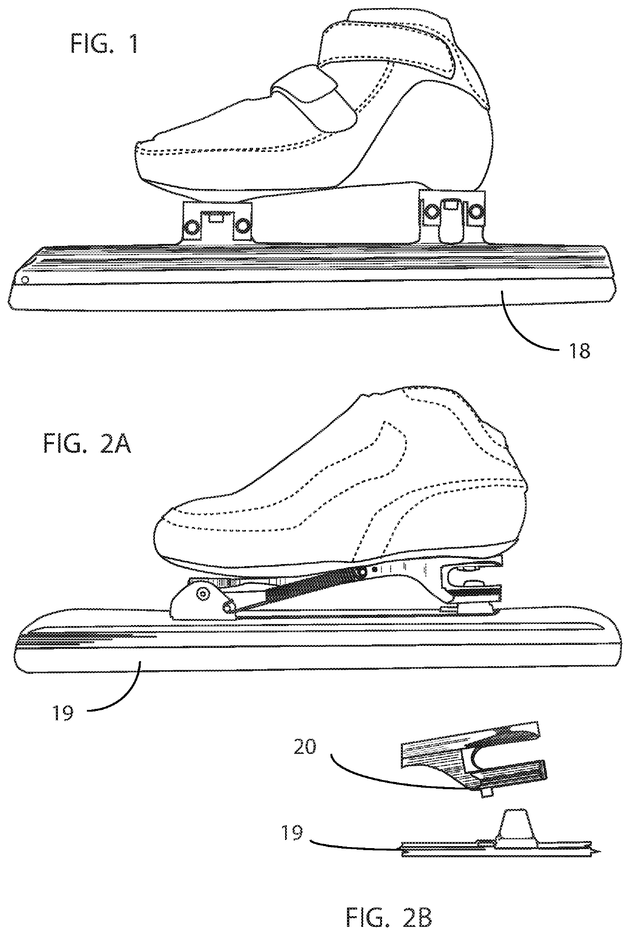
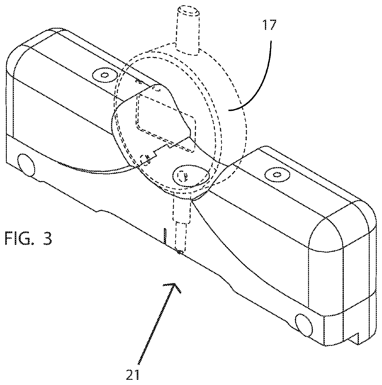
[0057]In FIG. 3, a front perspective view is shown of an embodiment of a blade measuring apparatus, with an associated dial indicator (17). The measuring apparatus can be used for measuring a short track skate blade (18) or a long track skate blade (19), examples of which are shown in FIGS. 1 and 2A. The skate blades (18) and (19) are generally configured as an elongated rail-type support, which is typically a cylindrical tube shape with appendages to facilitate mounting of a blade runner component and mounting points for affixing boots, commonly referred to as a blade tube. The blade tube generally has a slot adapted to hold and retain the upper portion of the blade or runner on one side of the blade tube, and mounting platform(s) referred to as “cups” or “arms” attached on the opposite side of the blade tube for attaching the blade assembly to boots. The short track blade (18) and long track blade (19) shown in FIGS. 1 and 2A exemplify one possible embodiment of each type of skate...


PUM


Abstract

A blade measuring apparatus (21) to measure the radius and bend of skate blades along the longitudinal plane of the skate blade runner features a one-piece frame (1), thermally non-conductive handles (5), and adjustable, replaceable, and interchangeable magnetic force application components (9, 10) and assemblies.

Description

CROSS REFERENCES TO RELATED APPLICATIONS[0001]The present application claims priority as a national phase entry under 35 U.S.C. § 371 of PCT Application number PCT / US2017 / 058065, which in turn claims priority to U.S. Provisional Application No. 62 / 412,097, filed Oct. 24, 2016. This Application incorporates both prior Applications by reference herein in its entirety.FIELD OF THE INVENTION[0002]The invention discussed herein relates to the general field of ice-skating accessories and describes a skate blade measuring device.BACKGROUND OF THE INVENTION[0003]The curved speed skate blade was first discussed in U.S. Pat. No. 5,320,368 (1994) to Ling. The patent discusses some of the advantages with longitudinal side bending of speed skating blades, including combinations of radius and bend for speed skating blades in said patent.[0004]Speed skating blades are generally manufactured with an aluminum or steel longitudinal tubular structure, into which a steel blade is mounted on one side of...

Claims


Application Information

Patent Timeline
Patent Type & Authority Patents(United States)
IPC IPC(8): G01B5/213A63C1/40A63C1/38A63C3/00G01B5/00A63C1/32
CPCA63C1/32A63C3/00G01B5/213G01B5/0023A63C1/38G01B5/0004A63C1/40A63C2203/18G01B3/22
Inventor DI NARDO, THOMASNEEDHAM, CHRISTOPHERGOMM, MICHAELLAURIDSEN, CHRIS
Owner MAYFLOWER INDUCTRIES LLC
Why Eureka
Try Eureka