System and method for controlling leak

a technology of leakage control and leakage control, applied in the direction of valve details, valve arrangement, other medical devices, etc., can solve the problem of not being able to adjust, and achieve the effect of facilitating the adjustment of one or more properties

Active Publication Date: 2020-03-03
KONINKLJIJKE PHILIPS NV
View PDF12 Cites 1 Cited by
  • Summary
  • Abstract
  • Description
  • Claims
  • Application Information

AI Technical Summary

Benefits of technology

[0004]Accordingly, one or more aspects of the present disclosure relate to an adjustable leak valve configured to control leak during respiratory therapy. The valve comprises a tubular body, a sleeve, a dial, and / or other components. The tubular body is formed along a first axis of the valve. The tubular body has a first end, a second end, and a wall. The tubular body forms a flow path configured to conduct gas between the first end and the second end during respiratory therapy. The tubular body has body orifices formed in the wall that communicate gas from the flow path through the wall. The sleeve is rotatable about the first axis with respect to the tubular body. The sleeve substantially surrounds the body orifices in the body. The sleeve has sleeve orifices formed therein. The sleeve orifices are formed in the sleeve and are positionable to overlap with the body orifices. The dial has a tubular shape. The dial is rotatable about the first axis relative to the sleeve. The dial substantially surrounds the sleeve orifices in the sleeve. The dial has a dial orifice formed therein. The dial orifice is formed in the dial and positionable to overlap with the sleeve orifices and the body orifices. Rotational coupling between the tubular body, the sleeve, and the dial facilitates adjustable configuration of one or more properties of a leak pathway formed by positioning the overlapping of the dial orifice with at least one of the sleeve orifices and at least one of the body orifices to allow leak during respiratory therapy.
[0005]Another aspect of the present disclosure relates to a method for controlling leak during respiratory therapy with an adjustable leak valve. The valve comprises a tubular body, the tubular body extending along a first axis of the valve, the tubular body having a first end, a second end, a wall, and a flow path configured to conduct gas between the first end and the second end during respiratory therapy, the tubular body having body orifices formed in the wall that communicate gas from the flow path through the wall; a sleeve, the sleeve substantially surrounding the body orifices in the body, the sleeve having sleeve orifices formed therein, and a dial, the dial having a tubular shape, the dial substantially surrounding the sleeve orifices in the sleeve, the dial having a dial orifice formed therein. The method comprises rotating the sleeve about the first axis, the sleeve orifices being positionable to overlap with the body orifices; rotating the dial about the first axis, the dial orifice being positionable to overlap with the sleeve orifices and the body orifices; and facilitating adjustable configuration of one or more properties of a leak pathway formed by positioning the dial orifice to overlap with at least one of the sleeve orifices and at least one of the body orifices to allow leak during respiratory therapy.
[0006]Still another aspect of the present disclosure relates to a valve configured to control leak during respiratory therapy. The valve comprises means for forming a flow path, the means for forming a flow path formed along a first axis of the valve and having a first end, a second end, and a wall, the means for forming a flow path configured to conduct gas between the first end and the second end during respiratory therapy, the means for forming a flow path having body orifices formed in the wall that communicate gas from the flow path through the wall; means for substantially surrounding the body orifices, the means for substantially surrounding the body orifices rotatable about the first axis with respect to the means for forming a flow path, the means for substantially surrounding the body orifices having sleeve orifices formed therein, the sleeve orifices being formed in the means for substantially surrounding the body orifices and being positionable to overlap along the first axis with the body orifices; and means for substantially surrounding the sleeve orifices, the means for substantially surrounding the sleeve orifices having a tubular shape, the means for substantially surrounding the sleeve orifices being rotatable about the first axis with respect to the means for substantially surrounding the body orifices, the means for substantially surrounding the sleeve orifices substantially surrounding the sleeve orifices, the means for substantially surrounding the sleeve orifices having a dial orifice formed therein, the dial orifice being formed in the means for substantially surrounding the sleeve orifices and positionable to overlap with the sleeve orifices and the body orifices. Rotational coupling between the means for forming a flow path, the means for substantially surrounding the body orifices, and the means for substantially surrounding the sleeve orifices facilitates adjustable configuration of one or more properties of a leak pathway formed by positioning the overlapping of the dial orifice with at least one of the sleeve orifices and one of the body orifices to allow leak during respiratory therapy.

Problems solved by technology

Typically these valves allow a predetermined amount of leak at a given pressure and are not adjustable.

Method used


Image

  • System and method for controlling leak
  • System and method for controlling leak
  • System and method for controlling leak

Examples


Embodiment Construction

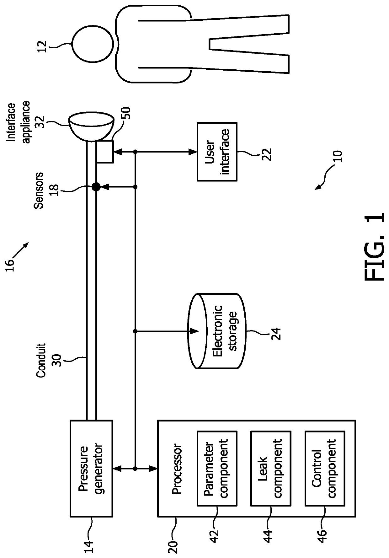
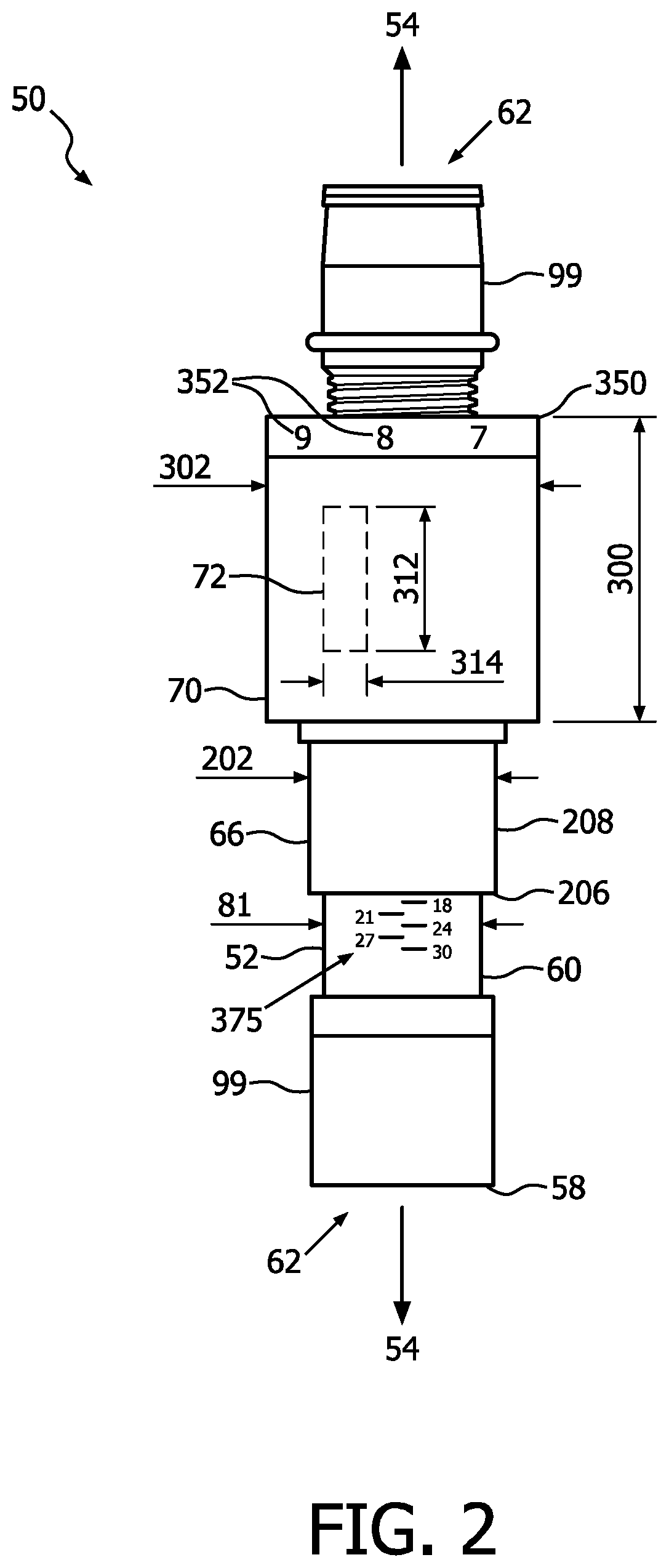
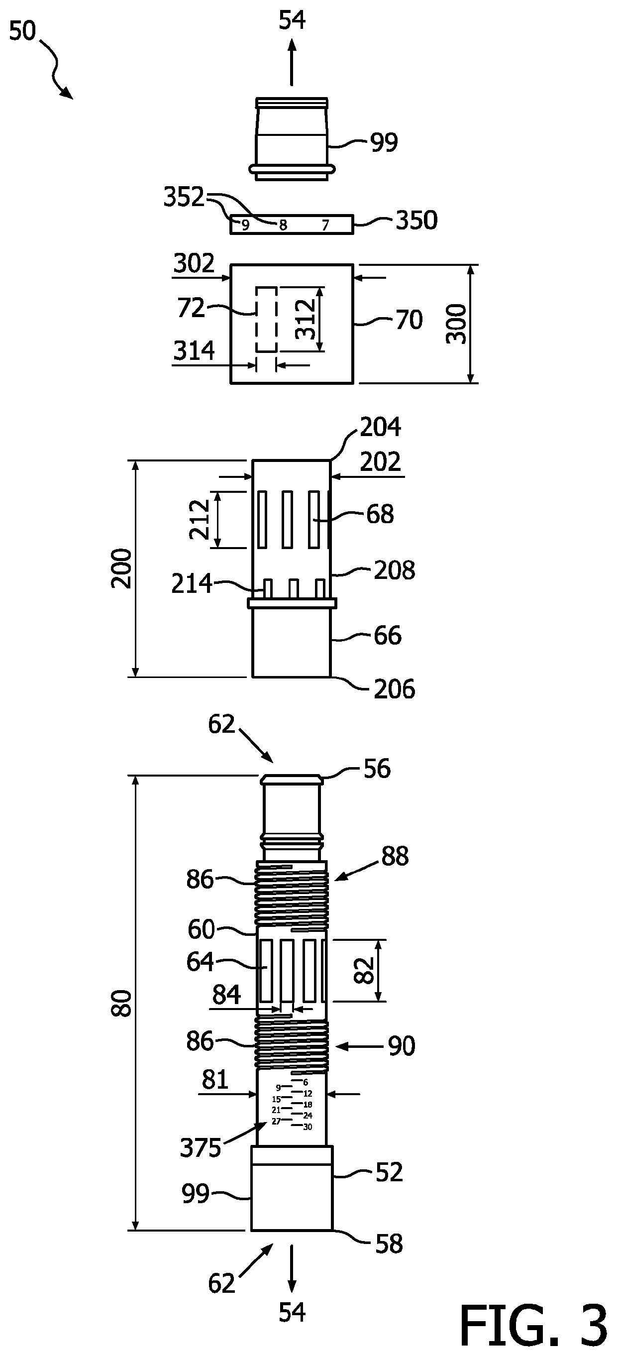
[0020]As used herein, the singular form of “a”, “an”, and “the” include plural references unless the context clearly dictates otherwise. As used herein, the statement that two or more parts or components are “coupled” shall mean that the parts are joined or operate together either directly or indirectly, i.e., through one or more intermediate parts or components, so long as a link occurs. As used herein, “directly coupled” means that two elements are directly in contact with each other. As used herein, “fixedly coupled” or “fixed” means that two components are coupled so as to move as one while maintaining a constant orientation relative to each other.

[0021]As used herein, the word “unitary” means a component is created as a single piece or unit. That is, a component that includes pieces that are created separately and then coupled together as a unit is not a “unitary” component or body. As employed herein, the statement that two or more parts or components “engage” one another shal...


PUM


Abstract

The present disclosure pertains to a system for controlling a leak flow rate during respiratory therapy. The system is configured to determine a leak flow rate necessary for CO2 expulsion for an individual subject and facilitate control of the leak flow rate during therapy such that the system exhausts substantially the entire exhaled volume of gas during an expiration of the subject. The system facilitates control of the leak flow rate during therapy via an adjustable leak valve. Determining the leak flow rate for the subject and facilitating control of the leak rate may minimize noise from air flow in the system, minimize the power draw needed by a pressure generator of the system, reduce a loss of medicine added to the respiratory therapy gas, and / or have other advantages, while still expelling the desired amount of CO2.

Description

CROSS-REFERENCE TO RELATED APPLICATIONS[0001]This patent application claims the priority benefit under 35 U.S.C § 371 of international patent application no. PCT / IB2015 / 057761, filed Oct. 10, 2015, which claims the priority benefit under 35 U.S.C. § 119(e) of U.S. Provisional Application No. 62 / 068,293 filed on Oct. 24, 2014, the contents of which are herein incorporated by reference.BACKGROUND OF THE INVENTION1. Field of the Invention[0002]The present disclosure pertains to a system and method for controlling leak during respiratory therapy.2. Description of the Related Art[0003]The inspiration of expired gases enriched with CO2 is called rebreathing, which has short and long term adverse effects on a subject including CO2 poisoning. Leak valves configured to exhaust these expired gases are known. Typically these valves allow a predetermined amount of leak at a given pressure and are not adjustable.SUMMARY OF THE INVENTION[0004]Accordingly, one or more aspects of the present disclo...

Claims


Application Information

Patent Timeline
Patent Type & Authority Patents(United States)
IPC IPC(8): A61M16/20F16K31/50F16K11/07A61M16/00F16K37/00
CPCA61M16/201F16K37/0016F16K11/0716F16K31/504A61M16/205A61M16/024A61M2205/15A61M2205/3337A61M2205/50
Inventor TRUSCHEL, WILLIAM ANTHONYCOLE, JR., KENNETH E.MCDERMOTT, MARKHOFFMAN, RAY
Owner KONINKLJIJKE PHILIPS NV
Why Eureka
Try Eureka