Eureka AIR delivers breakthrough ideas for toughest innovation challenges, trusted by R&D personnel around the world.

System for fixing the inner air deflector on deflective cover for rotating electrical machine

a technology for electrical machines and deflectors, which is applied in the direction of electrical apparatus, dynamo-electric machines, manufacturing dynamo-electric machines, etc., can solve the problem that the system is not developed for electric machines, and achieve the effect of minimizing losses caused by air turbulence, allowing assembly and disassembly of the deflector-cover-fan set, and better adjustment of the deflector position

Active Publication Date: 2020-03-03
WEG EQUIP ELETRICOS SA
View PDF23 Cites 0 Cited by
  • Summary
  • Abstract
  • Description
  • Claims
  • Application Information

AI Technical Summary

Benefits of technology

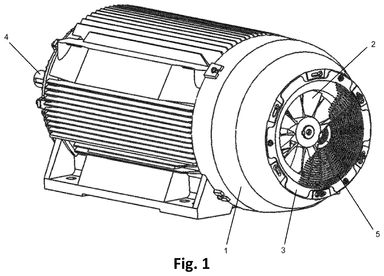
[0012]The invention circumvents the disadvantages inherent to the state of the art by revealing a SYSTEM FOR FIXING, which allows fixing of the deflector after mounting the deflective cover and the axial fan on the motor, thus enabling alignment of the inner part of the deflector with the outer part of the fan. This way, the gap between the fan blades and the inner deflector is adjusted, minimizing losses caused by air turbulence in this space.
[0013]Distinctly, this invention presents a new solution that consists of mounting the inner deflector after finishing the assembly of the other components of the electric machine, especially the fan and its deflective cover. Thus, there is flexibility for a better adjustment of the deflector position regarding the fan.
[0014]Another advantage of this new system is to allow assembly and disassembly of the deflector-cover-fan set without the need of specific tools or locking mechanisms for inner nuts during maintenance of the fan or deflector.
[0031]In a third system, fixing is performed with a fixing element (7) and a rectangular nut (9), and said nut must transpose the holes (1.1) of the deflective cover and the holes of the inner deflector (1.3). In the inner part of the deflector body there is a wall (1.2) that prevents the rotation of the nut when the fixing element is tightened by the outer part of the housing.

Problems solved by technology

However, the system was not developed for electric machines, but for switching fans.

Method used


Image

  • System for fixing the inner air deflector on deflective cover for rotating electrical machine
  • System for fixing the inner air deflector on deflective cover for rotating electrical machine
  • System for fixing the inner air deflector on deflective cover for rotating electrical machine

Examples


Embodiment Construction

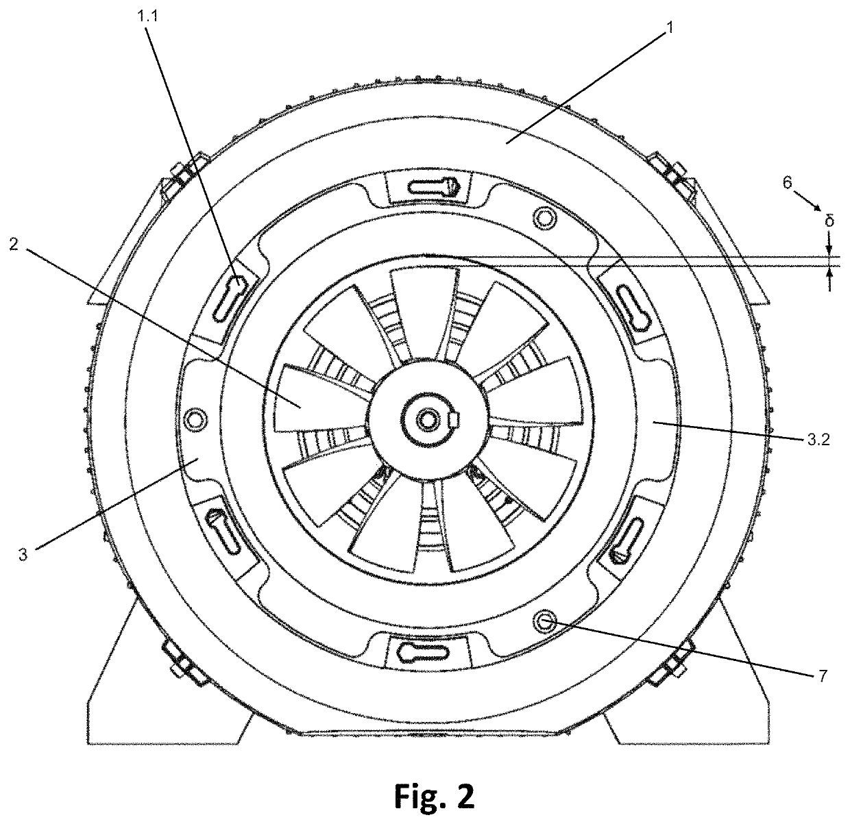
[0016]This invention consists of a system for fixing the inner air deflector (3) fixed on a deflective cover (1) for electric motors equipped with a fan (2), in order to enable the regulation of the gap (6) formed between the edges of the fan blades (2) and the inner part of the inner deflector body (3).

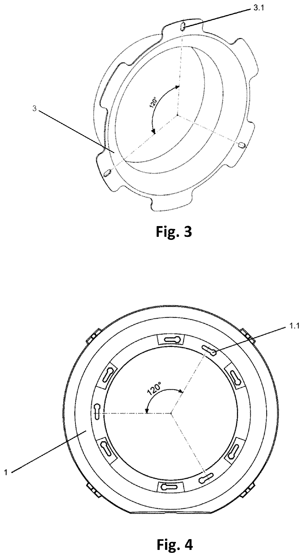
[0017]The inner deflector body (3) has from one to a plurality of flaps (3.2) with elongated holes (3.1) lagged equidistantly or not around the shaft of the electric machine.

[0018]Elongated holes (1.1) are understood as holes made on the flaps (3.2) of the deflector body (3) in order to allow the cover (1) to be fixed by the fixing elements (7 and 8). The elongated holes may feature various shapes that enable this fixing manner.

[0019]On a first shape, the elongated hole (1.1) features a rectangular shape, curved or not, with one of the edges allowing the passage of the fixing element body, but not the respective heads. FIG. 5 presents an elongated hole, not curved, with an edge allow...


PUM


Abstract

A system for fixing the inner air deflector on a deflective cover for a rotating electrical machine, wherein this deflector is fixed onto the deflective cover using a fixing element and a nut placed through elongated holes on flaps of the inner deflector and through elongated holes on the deflective cover, so that the tightening of the fixing set is performed from an outer part of the housing of the machine, enabling adjustment of a gap between an outer edge of blades of a fan and an inner surface of the inner air deflector, in order to minimize the effects of formation of counter-flowing air currents near the gap.

Description

FIELD OF APPLICATION[0001]The invention consists of a system for fixing the inner air deflector (3) on a deflective cover (1) for rotating electrical machine, wherein this deflector is fixed onto the deflective cover (1) using a screw (7) and a nut (8) placed by means of elongated holes (3.1) on the flaps (3.2) of the inner deflector (3) and elongated holes (1.1) on the deflective cover (1), so that the tightening of the nut-screw set is performed from the outer part of the housing, enabling adjustment of the gap (6) between the outer edge of the blades of the inner fan (2) and the inner surface of the inner air deflector (3) in order to minimize the effects of the formation of counter-flowing air currents near the gap (6).BACKGROUND OF THE INVENTION[0002]Electric machines should maintain a controlled operation temperature, in order to avoid physical damage and increase efficiency during work. Normally, the air cooling systems use a fan positioned on the inner side of the deflective...

Claims


Application Information

Patent Timeline
Patent Type & Authority Patents(United States)
IPC IPC(8): H02K15/00H02K9/06
CPCH02K15/0006H02K9/06
Inventor VERARDI, MARCELODILSON, PEDRO ZOZ
Owner WEG EQUIP ELETRICOS SA
Why Eureka
Eureka Blog
Learn More