
Apparatus For Decreasing Aerodynamic Drag, Improving Stability, and Reducing Road Spray of a Transportation Vehicle and Method of Mounting an Aerodynamic Add-On Device onto a Transport Vehicle

a technology for transport vehicles and add-on devices, which is applied in the field of land vehicles, can solve the problems of increasing fuel consumption, reducing fuel efficiency, and transport vehicles in motion experience a significant amount of aerodynamic drag, and achieve the effect of reducing aerodynamic drag on the transport vehicl

Inactive Publication Date: 2014-01-09
INNOVATIVE GLOBAL SYST
View PDF11 Cites 2 Cited by
  • Summary
  • Abstract
  • Description
  • Claims
  • Application Information

AI Technical Summary

Benefits of technology

[0013]It is an object of the present invention to provide an apparatus that minimizes aerodynamic drag on a transport vehicle.
[0014]It is yet another object of the present invention to provide an apparatus that minimizes air turbulence caused by the flow of air beneath a transport vehicle.
[0015]It is yet a further object of the present invention to provide an apparatus that minimizes aerodynamic drag while also allowing for the laminar flow of crosswind across the underside of a transport vehicle.

Problems solved by technology

It is well known that transport vehicles in motion experience a significant amount of aerodynamic drag (i.e., drag).
This aerodynamic drag greatly reduces fuel efficiency, leads to increased fuel consumption, and increases the cost of transporting items.
As the airflow enters the area of low pressure on the opposite side of the transport vehicle, it become turbulent, creates drag and reduces fuel efficiency.
Road spray can be annoying or dangerous to surrounding motorists because it tends to interfere with visibility.
A negative aspect of this crosswind airflow is that when the airflow reaches the area of low pressure on the downwind side of the transport vehicle, it becomes turbulent and creates aerodynamic drag.
The turbulence also can cause the transport vehicle to become unstable due to buffeting.
This instability can be both unsafe and fatiguing for the operator of the transport vehicle.
Some of the aforementioned aerodynamic add-on devices do not address the unique problems associated with the aerodynamic forces that crosswind exerts on a moving transport vehicle.
The design characteristics of some devices may work in non-crosswind conditions, but those same design characteristics may actually contribute to aerodynamic drag and instability in crosswind.
By inhibiting the lateral flow of crosswind beneath the transport vehicle, these devices potentially decrease stability and increase tipping forces (e.g., forces caused by crosswind having a tendency to tip over the transport vehicle), thereby resulting in danger to the operator of the transport vehicle as well as nearby motorists.
Although the rear bumper bar serves an important function of preventing underride collisions, it also creates aerodynamic drag by interfering with the smooth, organized (i.e., laminar) flow of air underneath and around the transport vehicle.
The resulting aerodynamic drag decreases the fuel efficiency of the transport vehicle.
In addition, existing rear bumper bars do nothing to help mitigate the drag resulting from turbulent airflow at the rear portion of a transport vehicle.
Many of these devices are bulky and difficult for just one person to install.
Installation can be further complicated by the fact that certain materials used to make these aerodynamic devices can contract and expand quite significantly in extreme temperatures.
The installation methods currently employed (e.g., bolting or riveting the aerodynamic device in place) generally inhibit the ability of the aerodynamic device to expand and / or contract.
As a result, such installation methods necessitate the use of materials which tend to not expand or contract, which materials are generally more expensive and heavier than alternative materials.

Method used


Image

  • Apparatus For Decreasing Aerodynamic Drag, Improving Stability, and Reducing Road Spray of a Transportation Vehicle and Method of Mounting an Aerodynamic Add-On Device onto a Transport Vehicle
  • Apparatus For Decreasing Aerodynamic Drag, Improving Stability, and Reducing Road Spray of a Transportation Vehicle and Method of Mounting an Aerodynamic Add-On Device onto a Transport Vehicle
  • Apparatus For Decreasing Aerodynamic Drag, Improving Stability, and Reducing Road Spray of a Transportation Vehicle and Method of Mounting an Aerodynamic Add-On Device onto a Transport Vehicle

Examples


Embodiment Construction

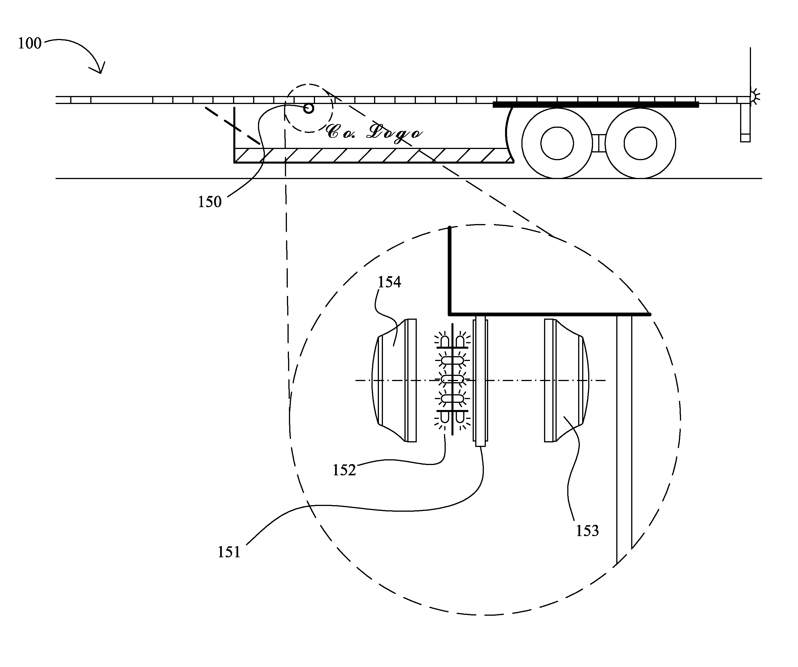
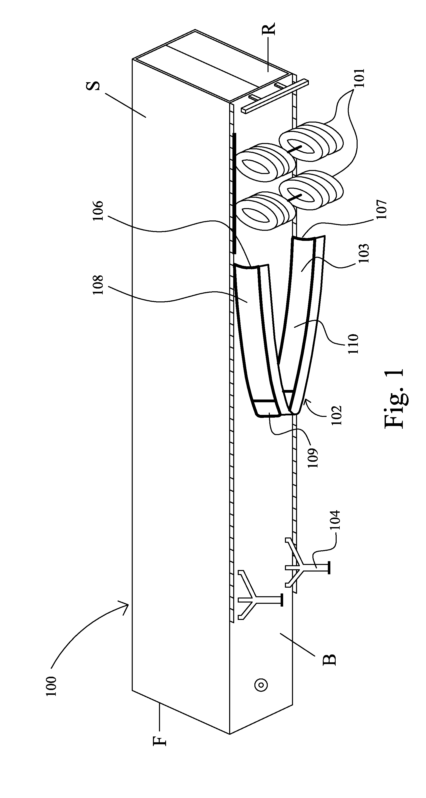
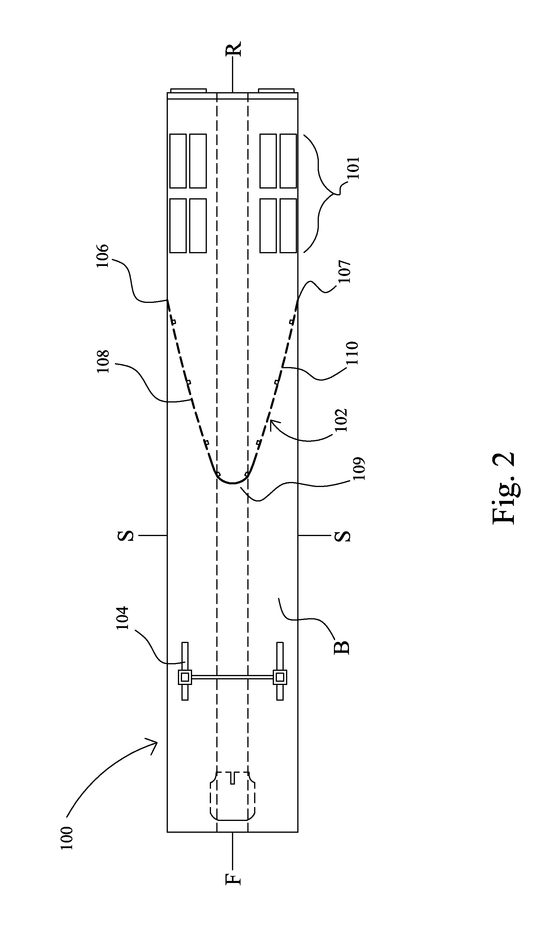
[0056]The apparatus and method according to the present invention will typically be used in connection with transport vehicles having a front F, a rear R, a bottom B (i.e., underbody, undercarriage, underside), and opposing sides S. The transport vehicle typically has at least one front wheel assembly (i.e., a wheel assembly (i.e., combination of an axle, rims and tires) positioned near the front portion of the transport vehicle and substantially supporting the front portion of the transport vehicle) and at least one rear wheel assembly (i.e., a wheel assembly positioned near the rear portion of the transport vehicle and substantially supporting the rear portion of the transport vehicle). The rearmost front wheel assembly is that front wheel assembly which is nearest the rear of the transport vehicle. The frontmost rear wheel assembly is that rear wheel assembly which is nearest the front of the transport vehicle. The inside wheelbase is the distance from the most rearward axle of t...


PUM


Abstract

The invention relates to an apparatus for decreasing aerodynamic drag, improving stability, and reducing road spray of a transport vehicle. The apparatus comprises an underbody fairing comprising a substantially parabolic elongated panel. The underbody fairing is strategically positioned beneath the transport vehicle and forward of the rear wheel assembly to deflect air around the rear wheel assembly while also facilitating a laminar airflow moving laterally beneath the transport vehicle.

Description

CROSS-REFERENCE TO PRIORITY APPLICATIONS[0001]This U.S. nonprovisional application claims the benefit of, and incorporates entirely by reference, commonly owned U.S. Provisional Patent Applications Ser. No. 61 / 373,565, for Apparatus and System for Reducing Drag and Increasing Stability of a Transport Vehicle, filed on Aug. 13, 2010; Ser. No. 61 / 455,704, for System and Method for Mounting Structural Add-ons for Heavy Duty Vehicles, filed on Oct. 25, 2010; Ser. No. 61 / 425,332, for Apparatus and System for Reducing Drag and Increasing Stability of a Transport Vehicle, filed on Dec. 21, 2010; Ser. No. 61 / 426,817, for System and Method for Mounting Structural Add-ons for Heavy Duty Vehicles, filed on Feb. 8, 2011; and Ser. No. 61 / 464,400, for System and Method for Improving Vehicle Aerodynamics and Fuel Efficiency, filed on Mar. 3, 2011.FIELD OF THE INVENTION[0002]The invention relates generally to land vehicles with distinct wind deflectors. More particularly, the invention relates to a...

Claims


Application Information

Patent Timeline
Patent Type & Authority Applications(United States)
IPC IPC(8): G07C5/00B62D35/00B60Q1/32
CPCG07C5/008B60Q1/32B62D35/001B62D35/007B62D35/02
Inventor LESESKY, ALAN C.
Owner INNOVATIVE GLOBAL SYST
Learn More