Clamping apparatus

Active Publication Date: 2020-03-24
FAN EAGLE
View PDF13 Cites 16 Cited by
  • Summary
  • Abstract
  • Description
  • Claims
  • Application Information

AI Technical Summary

Benefits of technology

[0014]The present invention has a simple structure including a single main pinion respectively meshed with the two clamping arms and the first and second manual actuators, which has a lower manufacture cost. Upon a

Problems solved by technology

However, the unidirectional limiting unit of the aforementioned structure is small in size, and may not be easily actuated for releasing the locking state after placement of a portable electronic product.
Unfortun

Method used


Image

  • Clamping apparatus
  • Clamping apparatus
  • Clamping apparatus

Examples


Example

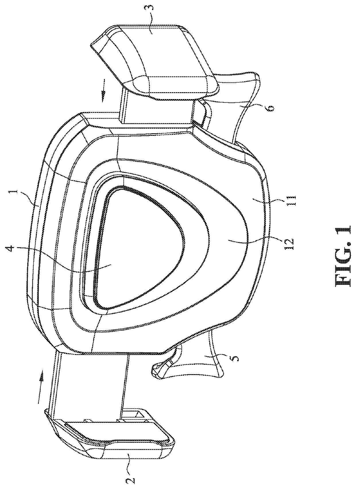
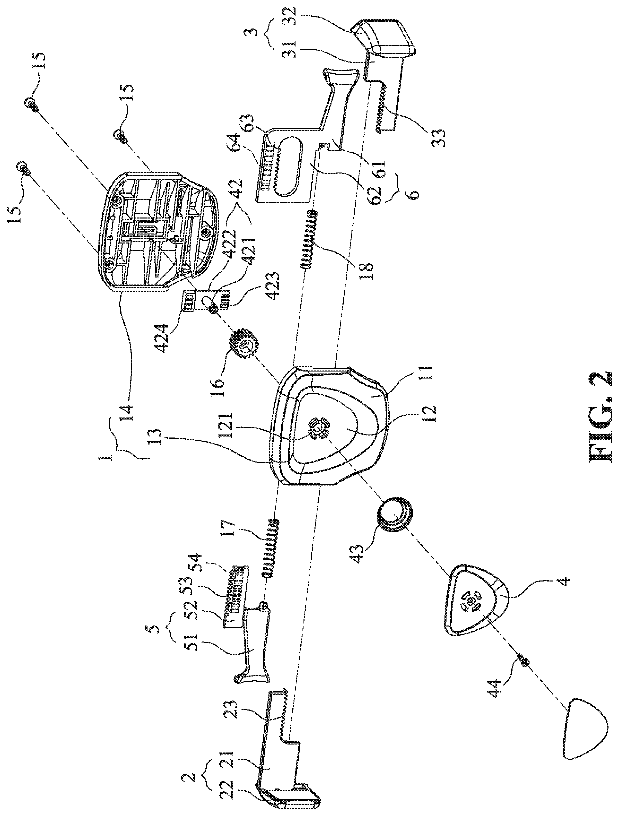
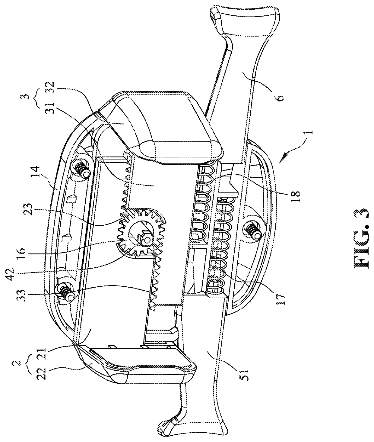
[0023]FIG. 1 is a perspective showing an embodiment of the present invention. A clamping apparatus according to the present invention includes a housing 1, two clamping arms 2 and 3, a push member 4, and at least a manual actuator. In the illustrated embodiment, two manual actuators are provided, which include a first and a second manual actuators 5 and 6 respectively disposed at two sides of the housing 1. It will be appreciated, however, that a variant embodiment may provide only one manual actuator. The housing 1 externally has a receiving area 11 having a recessed region 12. The push member 4 is located in the recessed region 12, and is movable upward and downward within a short range of displacement. A locking state can be released when the push member 4 is depressed toward the interior of the recessed region 12, whereby allowing the two clamping arms 2 and 3 to move toward a central region and clamp a mobile device while the first and second manual actuators 5 and 6 concurrent...


PUM


Abstract

A clamping apparatus includes a housing, two clamping arms, at least one manual actuator and a push member. The housing has a receiving area provided with a recessed region. The two clamping arms are assembled with the housing at two sides thereof, and are movably linked to each other via a main pinion disposed inside the housing. The push member is disposed in the recessed region and protrudes partially from the receiving area. When the push member is pressed toward an interior of the recessed region, the initial locking state is released so that the two clamping arms can move for clamping a mobile device. The manual actuator is assembled with the housing at a side thereof, and extends partially into the housing to mesh with the main pinion. A user can operate the manual actuator to concurrently drive the two clamping arms to open via the main pinion.

Description

BACKGROUND OF THE INVENTION1. Field of the Invention[0001]The present invention relates to clamping apparatuses, and more particularly to a clamping apparatus for a mobile device that is convenient in use.2. The Prior Arts[0002]Electronic mobile devices such as smartphones, satellite navigators, drive recorders and audio-video players can be typically used with a clamping apparatus, which allows a user to operate the mobile device in a vehicle or indoor without the need of holding the mobile device.[0003]The inventor of the present application previously designed a clamping apparatus suitable for use with a portable electronic product, which includes a housing, two clamping units, a unidirectional limiting unit and a manual actuating unit. The housing has a receiving area adapted to receive the placement of a portable electronic product. The two clamping units are appended to two sides of the housing, and can slide transversally in a concurrent manner for opening or closing the clam...

Claims


Application Information

Patent Timeline
IPC IPC(8): F16B2/12F16M13/02B60R11/02A47G29/08B60R11/00
CPCF16B2/12B60R11/0258B60R11/0241A47G29/08F16M13/022B60R11/0211B60R2011/0059B60R2011/0071B60R11/02F16M11/041F16M13/00
Inventor FAN, EAGLE
Owner FAN EAGLE
Why Eureka
Try Eureka