Heating cooker

a cooker and heat dissipation technology, applied in the field of heat dissipation cookers, can solve the problems of uneven heating and release of moisture in the cooking materials, and achieve the effect of more uniform cooking

Active Publication Date: 2020-03-31
PANASONIC INTELLECTUAL PROPERTY MANAGEMENT CO LTD
View PDF11 Cites 2 Cited by
  • Summary
  • Abstract
  • Description
  • Claims
  • Application Information

AI Technical Summary

Benefits of technology

[0008]In cases where the heating cooker of PTL 1 is used to cook relatively large cooking materials such as materials for french fries, such cooking materials are generally pushed toward the inner peripheral surface of the cooking container by pushing part 101 along with the rotation of stirring body 100 in rotating direction X100. The cooking materials pushed toward the inner peripheral surface of the cooking container go up to the apex of first slope 102A of turnover part 102 along first slope 102A as a result of their movement away from rotation axis A100 being restricted by the inner peripheral surface and fall along second slope 102B toward rotation axis A100. Here, turning force acts on these cooking materials, so that these cooking materials turn over. As a result, uneven heating is conceivably reduced.
[0010]However, as the heating proceeds, these cooking materials start to release moisture. This is when the cooking materials adhere easily to stirring body 100, and resistance from a bottom surface of the cooking container reduces. For this reason, it becomes difficult for pushing part 101 to move these cooking materials toward the inner peripheral surface of the cooking container, and it also becomes difficult for the cooking materials to go up first slope 102A of turnover part 102. Moreover, first slope 102A is provided to be parallel to a radial direction and thus does not have such a component as to direct the cooking materials toward rotation axis A100. For this reason, first slope 102A serves as a dam and thus easily causes the cooking materials to rotate together with stirring body 100. As a result, the same area of the cooking materials is continuously heated, thus resulting in uneven heating.
[0011]In cases where the heating cooker of PTL 2 is used to cook relatively small cooking materials such as minced onions, such cooking materials are generally pushed toward an inner peripheral surface of a cooking container by blade 201. The cooking materials pushed toward the inner peripheral surface of the cooking container move in such a manner as to climb over depression 201B because depression 201B is low-profile. This phenomenon takes place not only in an initial stage of heating but also in a later stage of heating because when the cooking materials increase in number near the inner peripheral surface of the cooking container, the cooking materials can climb over depression 201B with ease. Consequently, the cooking materials are restrained from rotating together with stirring body 200.
[0013]Therefore, there is still room for improvement in each of the heating cookers disclosed in PTL 1 and PTL 2 in view of more uniform cooking of both the relatively small and large cooking materials.
[0014]The present invention provides a heating cooker having a stirring function that is capable of more uniform cooking of both the relatively small and large cooking materials.

Problems solved by technology

However, as the heating proceeds, these cooking materials start to release moisture.
As a result, the same area of the cooking materials is continuously heated, thus resulting in uneven heating.

Method used


Image

  • Heating cooker
  • Heating cooker
  • Heating cooker

Examples


first exemplary embodiment

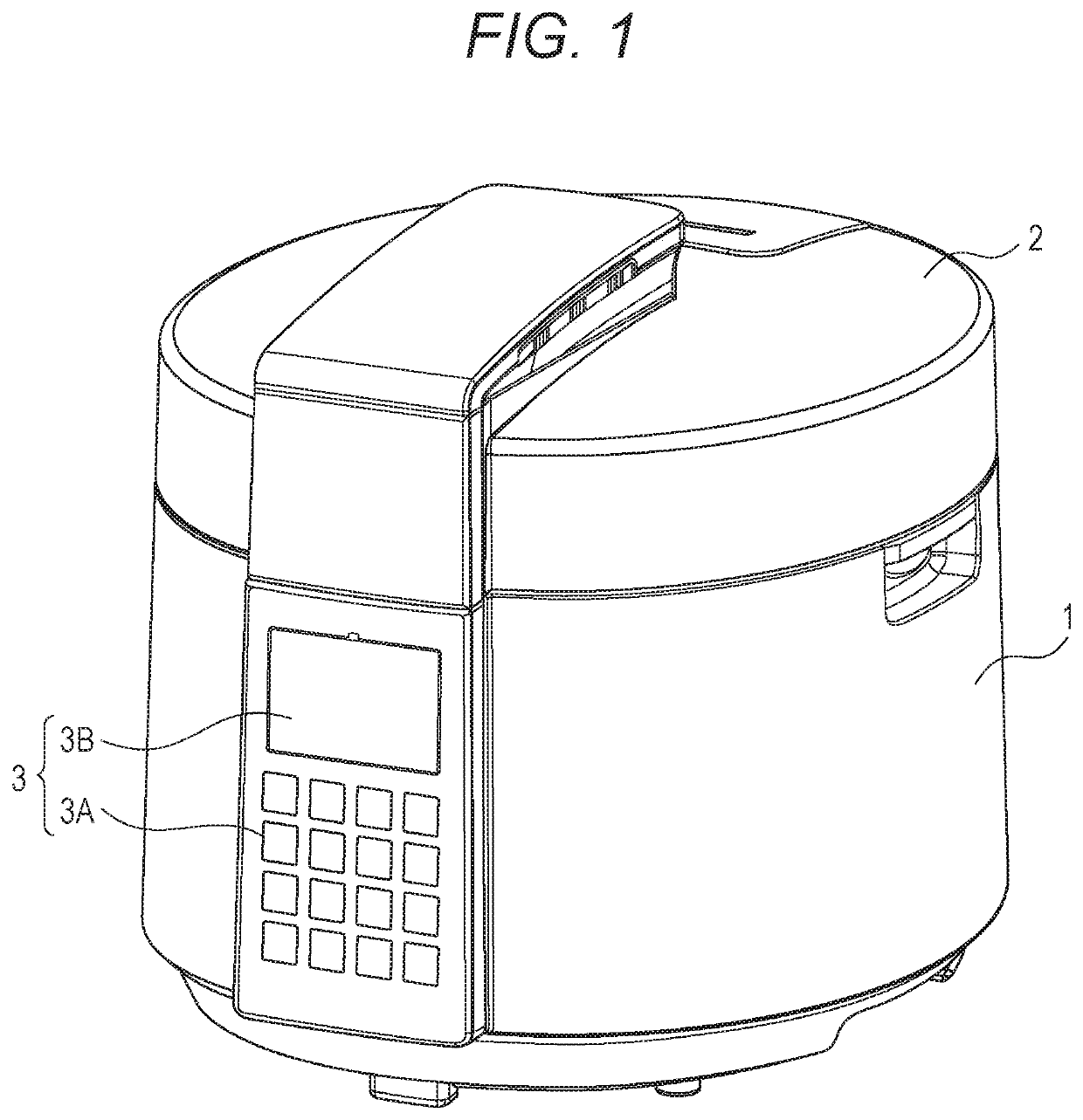
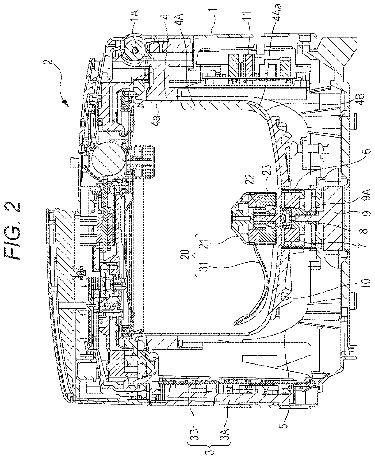
[0052]A heating cooker according to the first exemplary embodiment of the present invention is a heating cooker having a stirring function that includes a stirring body configured to stir cooking materials housed in a cooking container. FIG. 1 is a perspective view of the heating cooker according to the present exemplary embodiment. FIG. 2 is a sectional view of the heating cooker according to the present exemplary embodiment.

[0053]As shown in FIG. 1, the heating cooker of the present exemplary embodiment includes apparatus body 1 having a substantially bottomed cylindrical shape, and lid 2 that openably covers an upper opening of apparatus body 1. As shown in FIG. 2, lid 2 is rotatably mounted to hinge part 1A provided at an upper rear part (upper right in FIG. 2) of apparatus body 1.

[0054]Apparatus body 1 has, at its front, operation unit 3 provided for various operations including selection of a cooking menu. Operation unit 3 includes operation key group 3A and display 3B. Operat...

second exemplary embodiment

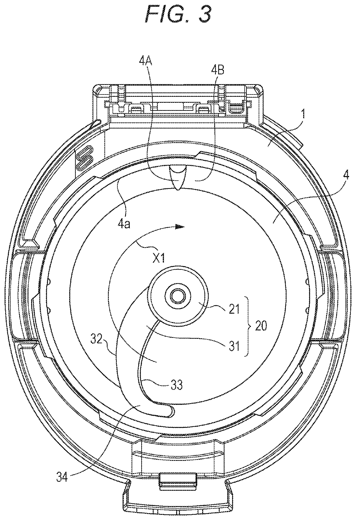
[0097]FIG. 12 is a sectional view of a heating cooker according to the second exemplary embodiment of the present invention. FIG. 13 is a plan view illustrating the heating cooker of FIG. 12 with a lid removed therefrom. FIG. 14 is a perspective view of a stirring body of the heating cooker of FIG. 12. The heating cooker of the second exemplary embodiment differs from the heating cooker of the first exemplary embodiment in that leading end portion 34 of blade 31 is provided with vertical wall 35 standing upward from front edge 32 along inner peripheral surface 4a of cooking container 4.

[0098]Vertical wall 35 functions to inhibit cooking materials that ride on third stirring region E3 along with rotation of blade 31 from falling toward and adhering to inner peripheral surface 4a of cooking container 4. In the present exemplary embodiment, a section corresponding to vertical wall 35 is referred to as “fourth stirring region E4” as shown in FIG. 14.

[0099]According to the heating cooker...


PUM


Abstract

A stirring body of the present invention includes housing rotatably mounted to a center of a bottom surface of a cooking container, and blade that extends from an outer peripheral surface of housing toward an inner peripheral surface of the cooking container and curves convexly toward a downstream side of a rotating direction in a plan view. Blade has front edge positioned on the downstream side in the rotating direction, and rear edge positioned on an upstream side in the rotating direction relative to front edge. A leading end portion of blade curves along the inner peripheral surface of the cooking container in the plan view and slopes upward toward the upstream side in the rotating direction. Front edge is positioned below rear edge near housing and is positioned above rear edge near leading end portion.

Description

[0001]This application is a 371 application of PCT / JP2016 / 003569 having an international filing date of Aug. 3, 2016, which claims priority to JP2015-167692 filed Aug. 27, 2015, the entire contents of which are incorporated herein by reference.TECHNICAL FIELD[0002]The present invention relates to a heating cooker having a stirring function that includes a stirring body configured to stir cooking materials in a cooking container.BACKGROUND ART[0003]Conventional heating cookers of this type are described with reference to FIGS. 15 to 17.[0004]FIG. 15 is a perspective view of a stirring body of one of the conventional heating cookers. As shown in FIG. 15, stirring body 100 includes pushing part 101 that pushes cooking materials toward an inner peripheral surface of a cooking container, and turnover part 102 that turns over the cooking materials positioned near the inner peripheral surface of the cooking container toward a center of the cooking container while stirring body 100 rotates ...

Claims


Application Information

Patent Timeline
Patent Type & Authority Patents(United States)
IPC IPC(8): A47J27/00A47J43/046A47J43/07A47J36/16
CPCA47J36/165A47J27/004A47J27/00A47J43/0722A47J43/046
Inventor OHTA, KATSUYUKINISHIMURA, MAKOTO
Owner PANASONIC INTELLECTUAL PROPERTY MANAGEMENT CO LTD
Why Eureka
Try Eureka