Check patentability & draft patents in minutes with Patsnap Eureka AI!

Rear subframe structure

a subframe structure and rear subframe technology, applied in the direction of vehicle components, resilient suspensions, pivoted suspension arms, etc., can solve the problems of difficult to secure high rigidity of front cross members and side members, and lack of detailed disclosure of arm support portions of upper arm and lower arm, etc., to achieve sufficient closed section structure and high rigidity

Active Publication Date: 2020-03-31
MAZDA MOTOR CORP
View PDF33 Cites 4 Cited by
  • Summary
  • Abstract
  • Description
  • Claims
  • Application Information

AI Technical Summary

Benefits of technology

The invention provides a rear subframe structure that allows for high rigidity of the front and side members while also providing space for an upper-arm and lower-arm support portions. The design also ensures a sufficient closed sectional structure in cases where the rear subframe is placed in a narrow space at the lower portion of a rear seat pan.

Problems solved by technology

It is difficult to support an upper arm and a lower arm, and to linearly extend a front cross member or a side cross member of a closed sectional structure with respect to a vehicle body support portion of a rear subframe.
Specifically, in a configuration, in which a rear subframe is disposed in a narrow space of a lower portion of a rear seat pan where it is impossible to connect a front cross member and a side member, while securing a sufficient closed sectional structure, it is difficult to secure high rigidity of a front cross member and a side member, and to secure a space for an upper-arm support portion and a lower-arm support portion.
However, in Patent Literature 2, there is no detailed disclosure about arm support portions of an upper arm and a lower arm.

Method used


Image

  • Rear subframe structure
  • Rear subframe structure
  • Rear subframe structure

Examples


Embodiment Construction

[0028]In the following, an embodiment of the present invention is described in detail based on the drawings.

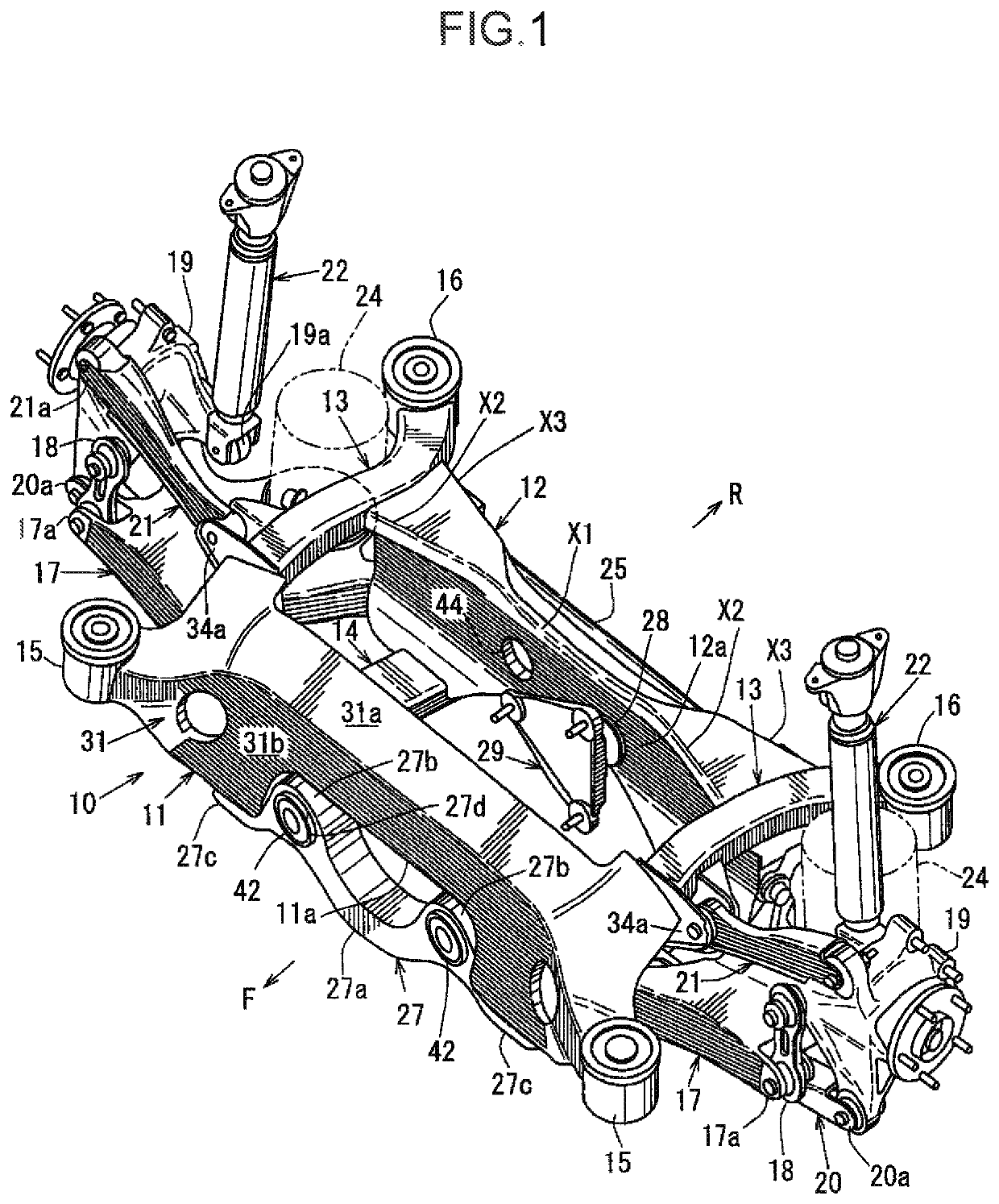
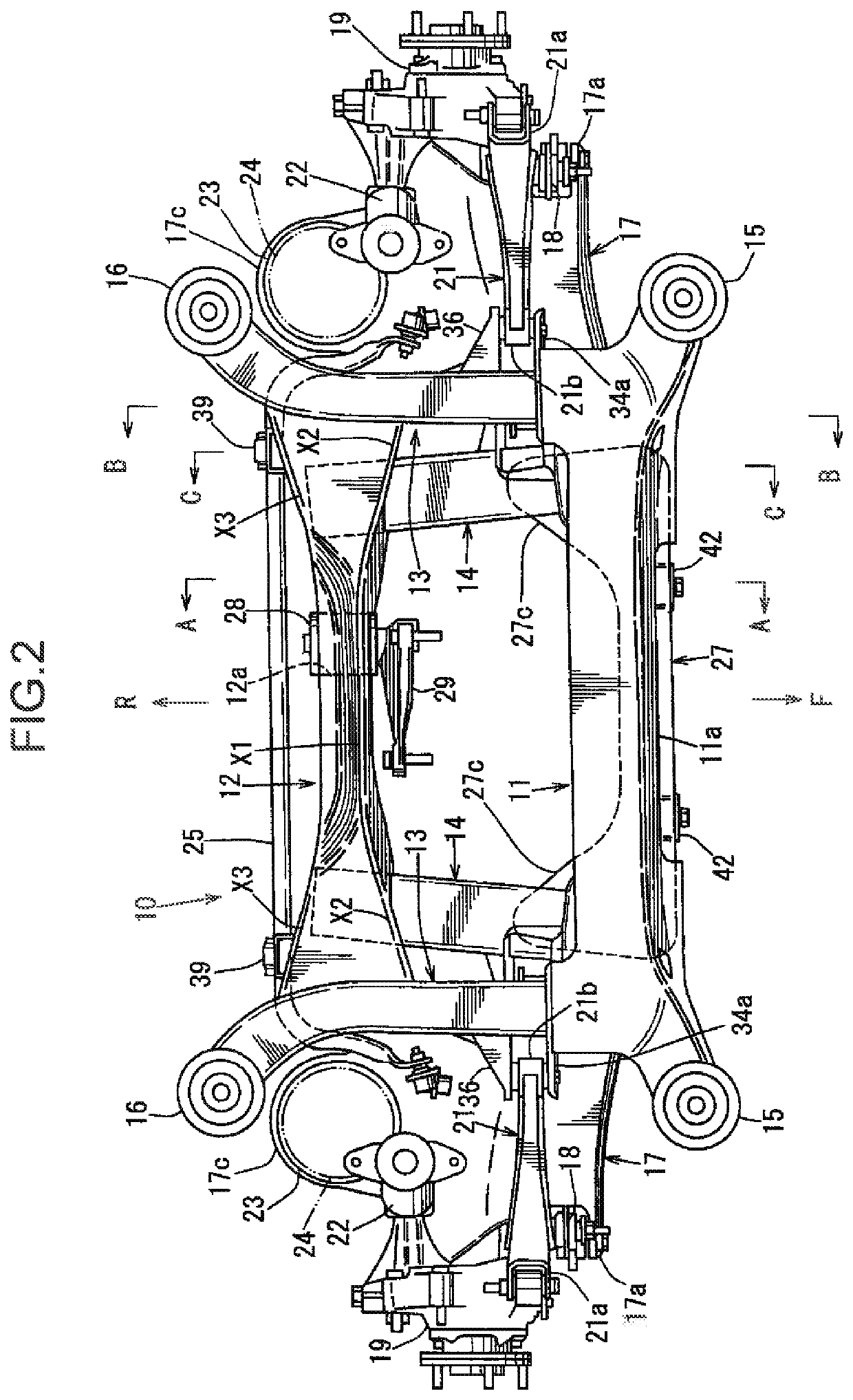
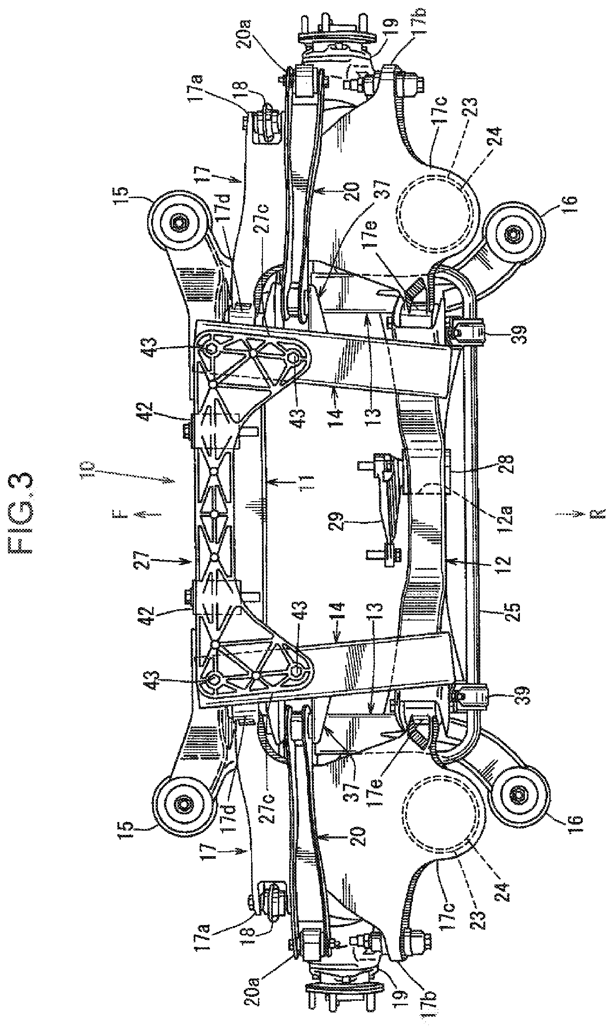
[0029]FIG. 1 is a perspective view of a rear subframe structure, FIG. 2 is a plan view of the rear subframe structure, FIG. 3 is a bottom view of the rear subframe structure, FIG. 4 is a front view of the rear subframe structure, and FIG. 5 is a rear view of the rear subframe structure. In FIG. 1, the arrow F indicates a vehicle front side, the arrow R indicates a vehicle rear side, the arrow IN indicates an inner side in a vehicle width direction, and the arrow OUT indicates an outer side in a vehicle width direction (the same definition is also applied to the other drawings).

[0030]Referring to FIG. 1 to FIG. 5, a rear subframe 10 for supporting a rear suspension includes a front cross member 11 extending in the vehicle width direction on the front side, a rear cross member 12 extending in the vehicle width direction on the rear side, a pair of upper side members 13 and 13 (h...


PUM


Abstract

A rear subframe structure is provided with a rear subframe configured such that a front cross member, a rear cross member, a pair of left and right upper side members, and a pair of left and right lower side members are connected; and a vehicle-body mounting portion formed on each of both ends of the front cross member, and on each of rear ends of the upper side members. The rear subframe further includes a vertical-wall-shaped pillar portion held and fixed between a lateral portion of the front cross member in the vehicle width direction and the upper side member, and extending in the vehicle width direction. A lower portion of the pillar portion is connected to the lower side member, an upper-arm support portion is formed on an upper portion of the pillar portion, and a lower-arm support portion is formed on a lower portion of the pillar portion.

Description

TECHNICAL FIELD[0001]The present invention relates to a rear subframe structure of a vehicle, and more particularly, to a rear subframe structure provided with a rear subframe configured such that a front cross member extending in a vehicle width direction, a rear cross member extending in the vehicle width direction on the rear side of the front cross member, a pair of left and right upper side members extending in a vehicle front-rear direction, and a pair of left and right lower side members extending in the vehicle front-rear direction are connected in a substantially grid pattern in a plan view of a vehicle; and a vehicle-body mounting portion formed on each of both ends of the front cross member in the vehicle width direction, and on each of rear ends of the upper side members.BACKGROUND ART[0002]Generally, in an integral type suspension provided with an integral link for controlling a swing trajectory (a so-called recession angle) of a rear wheel in a side view when the rear ...

Claims


Application Information

Patent Timeline
Patent Type & Authority Patents(United States)
IPC IPC(8): B62D21/00B60G3/20B62D21/11B60G99/00B60G7/02
CPCB60G99/002B60G3/20B62D21/11B60G7/02B60G2200/144B60G2206/60B60G2200/462B60G2204/15
Inventor TANAKA, MASAAKIKOMIYA, KATSUYUKI
Owner MAZDA MOTOR CORP
Features
  • R&D
  • Intellectual Property
  • Life Sciences
  • Materials
  • Tech Scout
  • Unparalleled Data Quality
  • Higher Quality Content
  • 60% Fewer Hallucinations
Learn More