Using packet tracing tool to automatically execute packet capture operations

a packet tracing and automatic execution technology, applied in the direction of electrical equipment, digital transmission, data switching networks, etc., can solve the problems of not only requiring excess work, and achieve the effect of reducing the number of packets captured and facilitating the correlation between the various packet captures

Active Publication Date: 2020-03-31
NICIRA
View PDF266 Cites 10 Cited by
  • Summary
  • Abstract
  • Description
  • Claims
  • Application Information

AI Technical Summary

Benefits of technology

[0007]In some embodiments, the packet capture commands are flow-specific—that is, the commands should limit the captured packets to only those belonging to the data flow(s) between the two endpoints. This limits the number of packets captured, makes correlation between the various packet captures easier, and ensures that a logical network administrator will not be provided access to packets for other logical networks.

Problems solved by technology

This not only requires excess work, but also requires the administrator to have direct access to these components.

Method used


Image

  • Using packet tracing tool to automatically execute packet capture operations
  • Using packet tracing tool to automatically execute packet capture operations
  • Using packet tracing tool to automatically execute packet capture operations

Examples


Embodiment Construction

[0018]In the following detailed description of the invention, numerous details, examples, and embodiments of the invention are set forth and described. However, it will be clear and apparent to one skilled in the art that the invention is not limited to the embodiments set forth and that the invention may be practiced without some of the specific details and examples discussed.

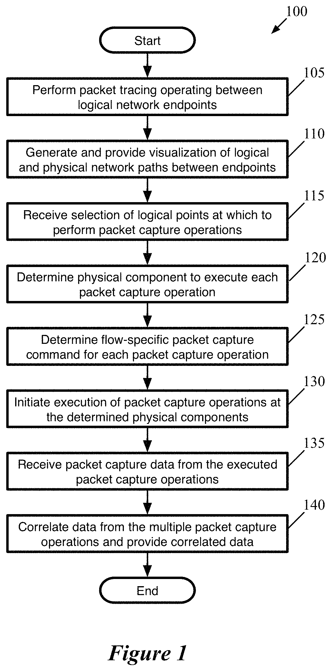
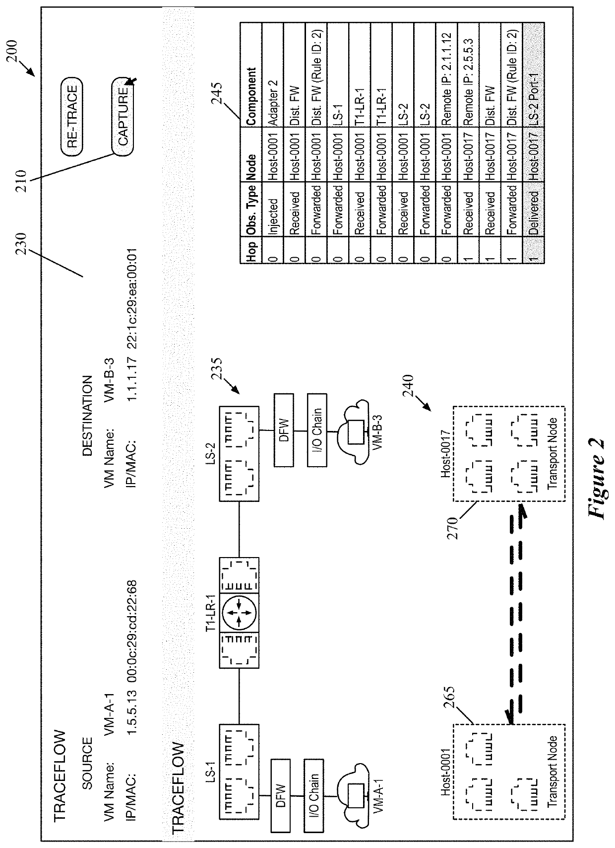
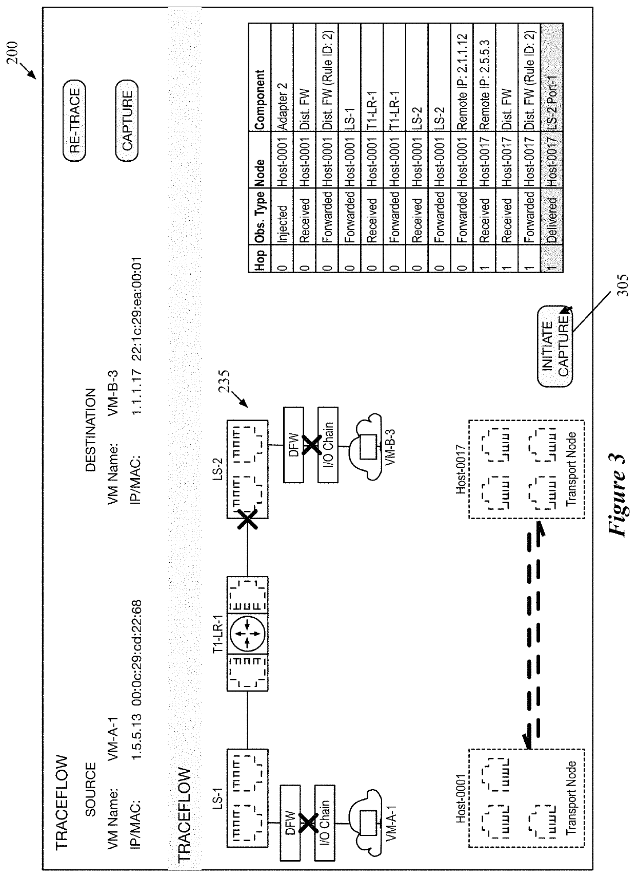
[0019]Some embodiments provide a method that enables automatic execution of packet capture operations at multiple points within a logical network datapath. In some embodiments, a user (e.g., a network administrator) initiates a packet tracing operation to identify logical and physical paths between specified source and destination logical network endpoints using a network management tool. The result of the packet tracing operation is a visualization of the logical network path between the endpoints, through various logical network components (e.g., logical switches, logical routers including centralized and di...


PUM


Abstract

Some embodiments provide a method that performs a packet tracing operation for a particular data flow between endpoints of a logical network to generate a representation of logical network components along a path between the endpoints. In response to a selection of at least two of the logical network components, the method automatically generates separate packet capture operations for execution by physical components that implement each of the selected logical network components. The method uses packet header information to correlate packet data from the separate packet capture operations.

Description

BACKGROUND[0001]Packet capture operations are a valuable tool in network troubleshooting. Using tcpdump or another tool, a network administrator can view the packets passing through a specific network location. However, in datacenters with multiple logical networks, much of the packet processing takes place in various components within the hypervisors, which perform packet processing operations for numerous isolated logical networks. An administrator of one logical network should be able to access packet data for other logical networks.[0002]Furthermore, if administrators want to capture packet data at multiple locations within the network, they are typically required to manually access these components and initiate the packet captures at the various locations. This not only requires excess work, but also requires the administrator to have direct access to these components.BRIEF SUMMARY[0003]Some embodiments provide a method that enables automatic execution of packet capture operati...

Claims


Application Information

Patent Timeline
Patent Type & Authority Patents(United States)
IPC IPC(8): H04L12/24H04L29/06H04L12/26H04L29/08H04L12/931
CPCH04L43/12H04L41/12H04L67/2814H04L43/04H04L69/22H04L41/0803H04L49/70H04L41/22H04L67/563H04L41/40
Inventor JAIN, JAYANTSENGUPTA, ANIRBANMANUGURI, SUBRAHMANYAMLUND, RICKTIAGI, ALOK
Owner NICIRA
Why Eureka
Try Eureka