
Wavelength and power scalable waveguiding-based infrared laser system

a waveguide and infrared laser technology, applied in the field of infrared fiber optics, can solve the problems of increasing limiting the mechanical mounting of the system, and limiting so as to reduce the complexity of the beam combined source, reduce the complexity of the system, and limit the number of failure points

Active Publication Date: 2014-01-16
THE UNITED STATES OF AMERICA AS REPRESENTED BY THE SECRETARY OF THE NAVY
View PDF1 Cites 8 Cited by
  • Summary
  • Abstract
  • Description
  • Claims
  • Application Information

AI Technical Summary

Benefits of technology

The present invention is a laser system that simplifies the process of combining beams in the mid-infrared and reduces the likelihood of failure. Compared to other laser systems, it has a smaller size and weight. The system has applications in various fields such as spectroscopy, LIDAR, and laser surgery. Overall, the invention is a more efficient and manageable laser system with fewer components and improved stability.

Problems solved by technology

Both approaches in the mid-IR and possible approaches in the long-wave-infrared have been limited to mechanically mounted beam steering elements such as minors and prisms.
Besides thermal and vibration requirements, the complexity of the system increases significantly with increasing number of ports.

Method used


Image

  • Wavelength and power scalable waveguiding-based infrared laser system
  • Wavelength and power scalable waveguiding-based infrared laser system
  • Wavelength and power scalable waveguiding-based infrared laser system

Examples


example 1

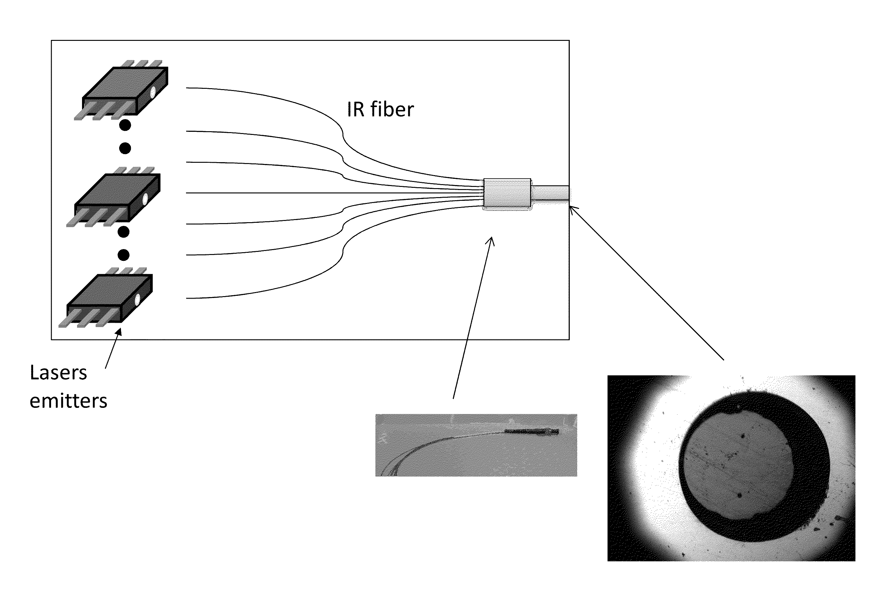
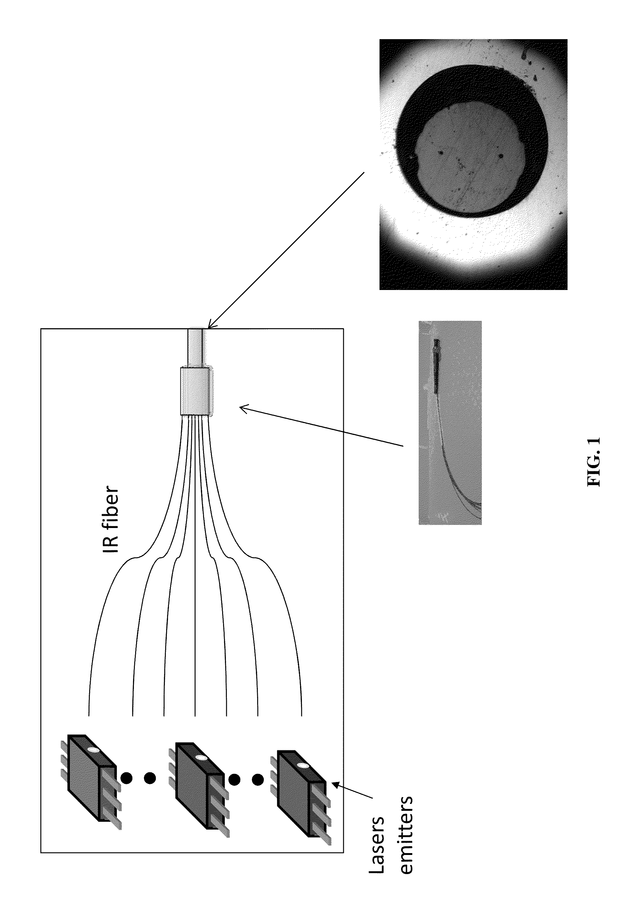
[0027]A quantum cascade laser with mid-IR emission (such as a laser emitter with wavelength centered around 4.6 μm) is coupled to a single mode chalcogenide optical fiber. A second quantum cascade laser with same emission wavelength and power is coupled to another identical optical fiber. Each optical fiber is fused together in a fiber based optical combiner, having a common output aperture and divergence. The coupling from each laser can be accomplished through a series of lenses, lensing of the output face of the optical fiber or direct optical bonding of the fiber to the emitter chip. Thermal and vibration isolation can be localized to the emitter to fiber region, not requiring coherence or stability across different laser emitters.

example 2

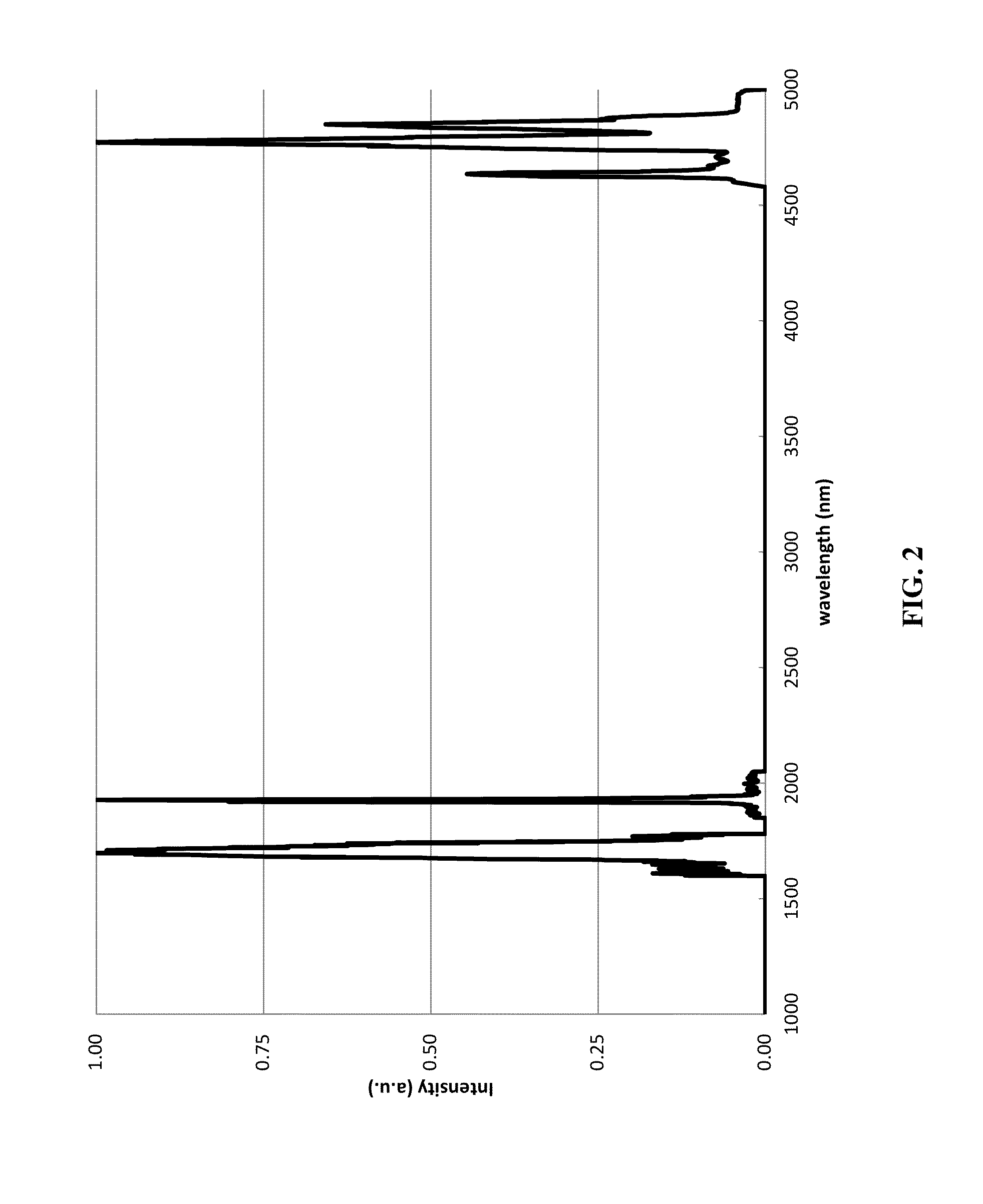
[0028]The system described in Example 1 where additional laser emitters at distinct wavelengths are added to the fiber combiner. Each laser emitter is coupled to a different fiber port, and the optical fibers can be multimode. FIG. 4 shows the endface of a multimode fiber coupler fabricated with chalcogenide fiber, prior to the fusion of all the cores.

example 3

[0029]A system of chip based laser emitters are fabricated in a single chip or bonded together onto a chip. The output of the laser emitters is routed into an array of waveguides in a silicon chip. The light is waveguided into an array waveguide grating and the output is coupled to a single output waveguide element.


PUM

PropertyMeasurementUnit
poweraaaaaaaaaa
laser poweraaaaaaaaaa
optical wavelengthsaaaaaaaaaa

Abstract

An infrared laser source system that combines laser emitters through an optical waveguide. Each emitter is coupled to a port of the optical waveguide and the waveguided signal is combined to provide a spatially combined laser source with a single common exit aperture. The materials used for waveguiding allow the propagation of wavelengths in the infrared. The system can be used for combining multiple laser emitters to increase the total output power and / or for combination of multiple emitters with different wavelength for increased spectral coverage out of the laser system.

Description

PRIORITY CLAIM[0001]This Application claims priority from U.S. Provisional Application No. 61 / 670,627 filed on Jul. 12, 2012 by Rafael Gattass et al., entitled “Infrared Optical Waveguide Combiner,” the entire contents of which are incorporated herein by reference.BACKGROUND OF THE INVENTION[0002]1. Field of the Invention[0003]The present invention relates generally to infrared fiber optics and, more specifically, to wavelength and power scalable waveguiding-based infrared laser systems.[0004]2. Description of the Prior Art[0005]Scientific advancements are constantly improving the availability of laser sources. In the infrared range, lasers are used for a myriad of applications such as but not limited to medical, sensing, defense, characterization, etc. However, applications continually drive the need for higher power or broader range laser systems with optical mode characteristics. In particular, for certain applications, the valuable metric is not solely power or spectral range, b...

Claims


Application Information

Patent Timeline
Patent Type & Authority Applications(United States)
IPC IPC(8): G02B27/10
CPCG02B27/10G02B27/1006G02B6/425G02B6/102G02B6/12019G02B6/2856Y10T29/49826
Inventor GATTASS, RAFAEL R.SHAW, LESLIE BRANDONSANGHERA, JASBINDER S.AGGARWAL, ISHWAR D.BUSSE, LYNDA E.
Owner THE UNITED STATES OF AMERICA AS REPRESENTED BY THE SECRETARY OF THE NAVY
Learn More