
Low complexity super-resolution technique for object detection in frequency modulation continuous wave radar

a frequency modulation, continuous wave radar technology, applied in the direction of reradiation, measurement devices, instruments, etc., can solve the problems of inability to find smaller objects in the presence of close by larger objects, inability to find small objects in the presence of larger objects, and inability to implement techniques in practice, etc., to reduce the computational complexity of the search, reduce the number of operating data points, and reduce the computational complexity

Active Publication Date: 2020-04-07
TEXAS INSTR INC
View PDF10 Cites 2 Cited by
  • Summary
  • Abstract
  • Description
  • Claims
  • Application Information

AI Technical Summary

Benefits of technology

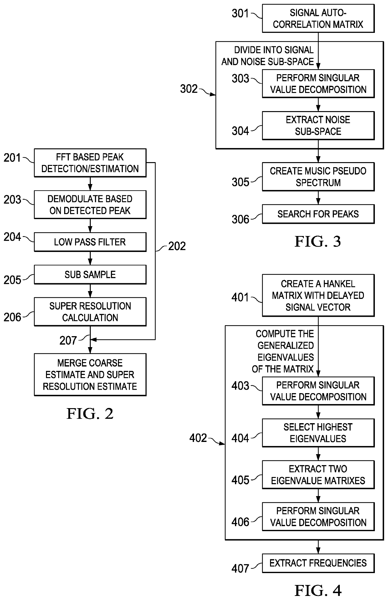
[0004]The solution to the computational problem is to perform an initial object detection using the classical method. In the context of FMCW (Frequency Modulated Continuous Wave) radar, this was done through Fast Fourier Transforms of the input data and then by searching for high valued amplitudes. Once potential objects are detected, super-resolution algorithms are performed around each of the detected objects or reflections. To reduce computational complexity of this search, the signal is demodulated so the detected object lies near DC values and then sub-sampled so the number of operating data points is reduced. The super-resolution technique then works on this reduced set of data thereby reducing computational complexity.

Problems solved by technology

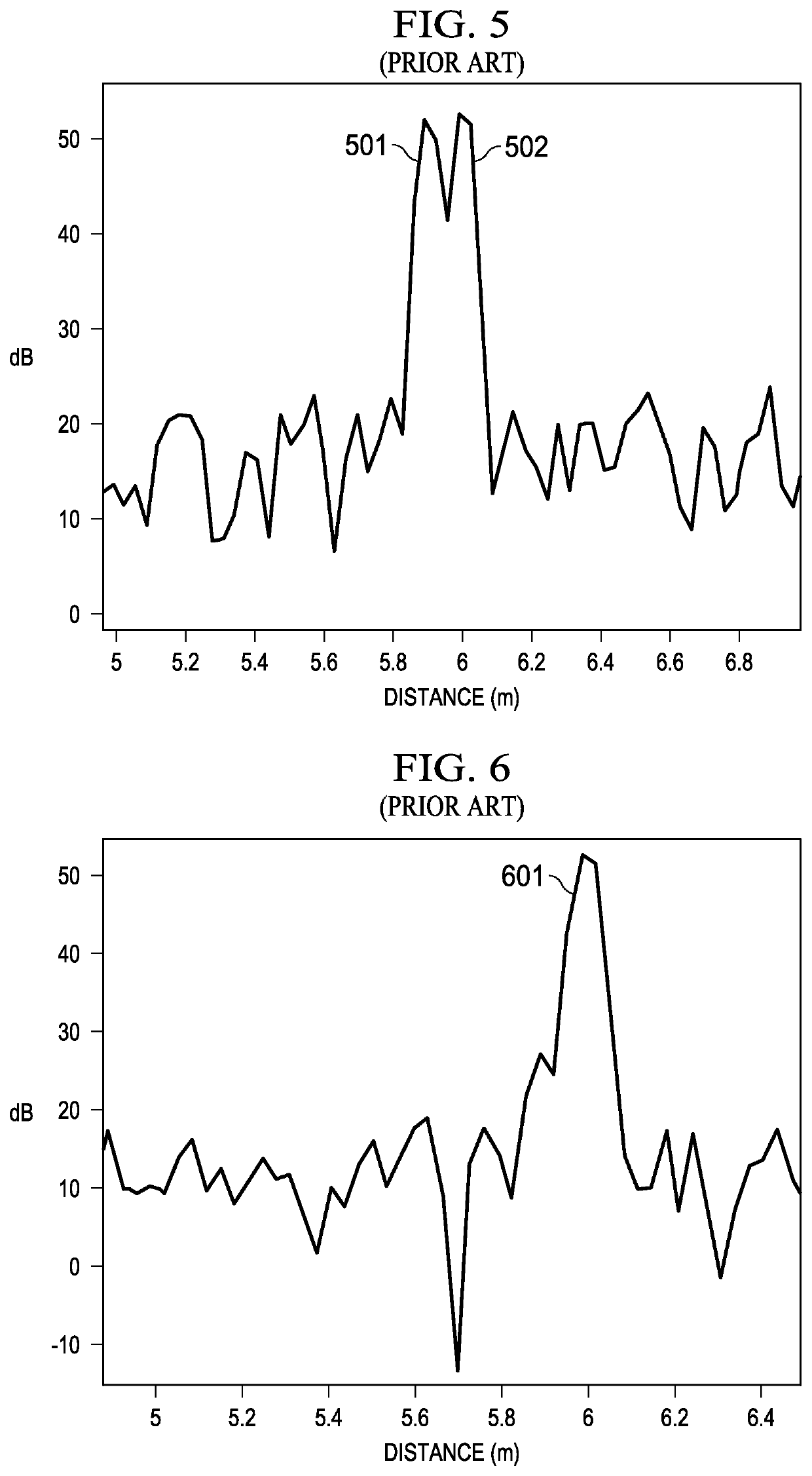
These techniques also often fail to find smaller objects in presence of close by larger objects.
However, these techniques are computationally expensive and rarely implemented in practice.

Method used


Image

  • Low complexity super-resolution technique for object detection in frequency modulation continuous wave radar
  • Low complexity super-resolution technique for object detection in frequency modulation continuous wave radar
  • Low complexity super-resolution technique for object detection in frequency modulation continuous wave radar

Examples


Embodiment Construction

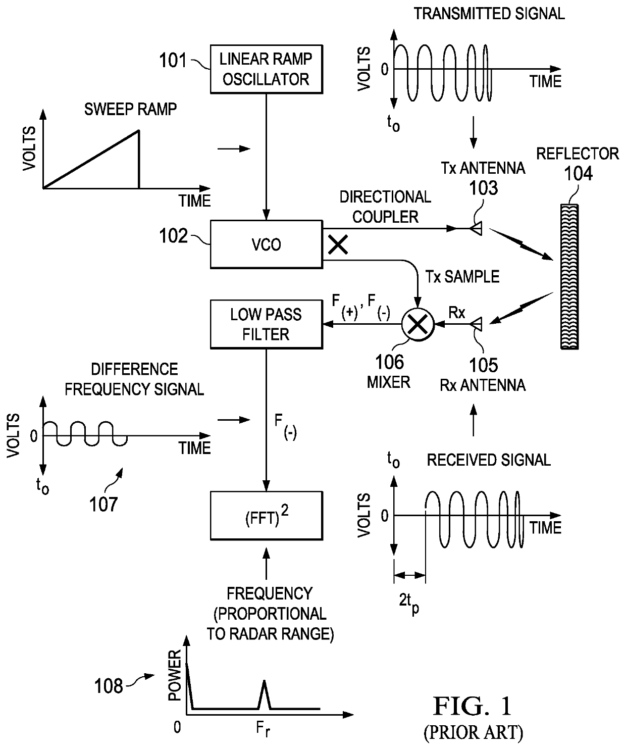
[0014]FMCW radars are often used to determine the location of an object and its speed of movement. These radars are used in automotive applications, industrial measurements, etc. A typical FMCW technique is shown in FIG. 1.

[0015]A chirp signal generated by ramp oscillator 101 and Voltage Controlled Oscillator (VCO) 102 (where the frequency is changed linearly) is transmitted by antenna 103 and reflected from object(s) 104. The reflected signal is received by antenna 105, mixed with transmitted signal in mixer 106 and the resulting beat frequency 107 is dependent on the distance of the object as given by

[0016]beat⁢⁢frequency=B⁡(2⁢R)Tr⁢c

Thus, if the beat frequency or frequencies for multiple objects can be estimated, the distances to those objects can be estimated. In the above equation, R is the range of the object, B is the bandwidth of the chirp signal, Tr is the time duration for the chirp and c is the speed of light.

[0017]In one commonly used object detection and distance estimat...


PUM


Abstract

In the proposed low complexity technique a hierarchical approach is created. An initial FFT based detection and range estimation gives a coarse range estimate of a group of objects within the Rayleigh limit or with varying sizes resulting from widely varying reflection strengths. For each group of detected peaks, demodulate the input to near DC, filter out other peaks (or other object groups) and decimate the signal to reduce the data size. Then perform super-resolution methods on this limited data size. The resulting distance estimations provide distance relative to the coarse estimation from the FFT processing.

Description

CLAIM OF PRIORITY[0001]This application claims priority under 35 U.S.C. 119(e) (1) to U.S. Provisional Application No. 62 / 162,405 filed May 15, 2015TECHNICAL FIELD OF THE INVENTION[0002]The technical field of this invention is radar object detection and corresponding object location determination.BACKGROUND OF THE INVENTION[0003]In classical object detection technique, the minimum distance to resolve two nearby objects (radar reflections) is limited by the so called Rayleigh distance. These techniques also often fail to find smaller objects in presence of close by larger objects. There exist several techniques known as super-resolution techniques to overcome these methods which can discriminate between objects even below the classical limits. However, these techniques are computationally expensive and rarely implemented in practice.SUMMARY OF THE INVENTION[0004]The solution to the computational problem is to perform an initial object detection using the classical method. In the cont...

Claims


Application Information

Patent Timeline
Patent Type & Authority Patents(United States)
IPC IPC(8): G01S13/34G01S7/35
CPCG01S7/352G01S13/343G01S2007/356G01S13/34G01S7/356
Inventor ALI, MURTAZAWANG, DANIKRAM, MUHAMMAD ZUBAIR
Owner TEXAS INSTR INC
Learn More