Exercise machine

a technology of exercise machines and resistance forces, applied in the field of exercise machines, can solve the problems of inability to keep the resisting force direction constant, cumbersome conventional exercise machines, and inhibiting the user from performing actions, so as to ensure the lightness and compactness of the machine, improve the direction accuracy, and increase safety

Active Publication Date: 2020-04-14
AKUIS SRL
View PDF8 Cites 0 Cited by
  • Summary
  • Abstract
  • Description
  • Claims
  • Application Information

AI Technical Summary

Benefits of technology

[0050]First of all among the several advantages of the invention, the resisting force direction perceived at the grip elements is controllable by the user and is automatically held at the specified value without additional actuators other than the resisting load sources. Optionally, the direction accuracy may be improved by dedicated sensors. Moreover the load vectoring system acts dynamically during an exercise allowing the implementation of a variable training curve in function of other parameters. Moreover, the vectoring system acts also as an automatic adjustment system that allows the user to quickly change between different kinds of exercises or assume different positions within the working area without the need to manually change the configuration of the machine. Furthermore, the load vectoring system may be used to set and hold the carriage at a specific position without the need to do it manually, allowing the user to perform exercises as in conventional cable machines having a fixed or selectable cable exit point.
[0051]The preferred resisting load source for this invention, being a non-conventional (for such type of exercise machine) compact electric motor linked to a winding drum where the cable is wound and un-wound during an exercise, allows dynamic control of resisting load magnitude and direction, ensures lightness and compactness of the machine and increases safety thanks to the capability of instantaneously turning off the load in case of emergency. This is associated with the capability of the electric motor to act also as a sensor suitable for measuring user movements during exercises and in particular recognizing specific user gestures made for controlling the machine behavior.
[0052]The preferred embodiment for at least one grip element, acting as an input device and user interface to the machine, through conventional means that in prior art were located on machine frame, enhances ergonomics and ease of use, and moreover increases safety of the device, allowing the user to activate the resisting load when ready and deactivating it at any time.
[0053]Said capabilities may be associated with another preferred security feature of the present invention that prevents or warns the user about machine instability or overturn risks that may arise in light machines not fixed to ground or walls.
[0054]One embodiment for the machine has the shape of a thin platform where the user positions itself to perform the exercise. All the mechanisms are hidden in said platform, improving the device safety by preventing the user from being harmed by machine moving parts. Being the platform lightweight and freely resting on the ground, it may be moved at will and stored when not in use.
[0055]Finally, the invention permits a modular approach, namely to use a combination of basic mechanisms above-mentioned to build more complex exercise machines and allow the addition of conventional or special equipment including benches, racks and pulley systems to invert the load direction.
[0056]These and other aspects, characteristics and advantages of the present disclosure will be better understood with reference to the following description, drawings and attached claims. The drawings, which are integrated and form part of the present description, show some forms of embodiment of the present invention, and together with the description, are intended to describe the principles of the disclosure.
[0057]The various aspects and characteristics described in the present description can be applied individually where possible. These individual aspects, for example aspects and characteristics described in the attached dependent claims, can be the object of divisional applications.
[0058]It is understood that any aspect or characteristic that is discovered, during the patenting process, to be already known, shall not be claimed and shall be the object of a disclaimer.

Problems solved by technology

It is noticeable the difficulty to keep constant the resisting force direction, as on the contrary naturally occurs in conventional weightlifting with free weights, where the resisting load direction always points to the ground (according to earth's gravity).
Moreover, conventional exercise machines are cumbersome (the support frame is considerably greater than the actual working area available to the user) and heavy (the total weight is considerably higher than the weight / load available for the exercise) for intrinsic, structural and safety reasons.
Moreover, in conventional exercise machines comprising some means used as user interface with the machine to perform common tasks including starting the exercise, changing the resisting load, interrupting the exercise, those means are located on the machine frame, inhibiting the user from performing actions on said user interface while doing an exercise.

Method used


Image

  • Exercise machine
  • Exercise machine
  • Exercise machine

Examples


embodiment 1

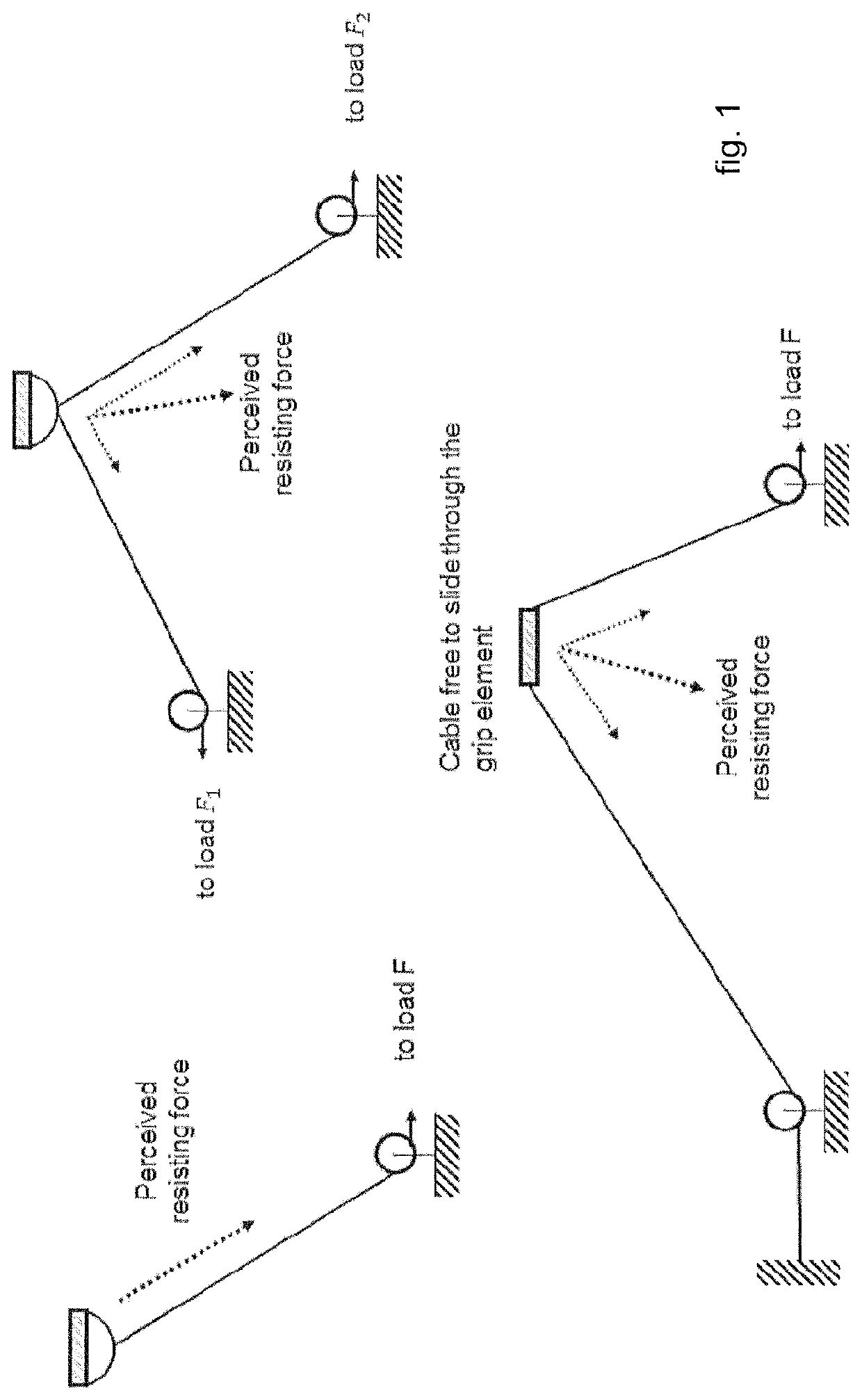
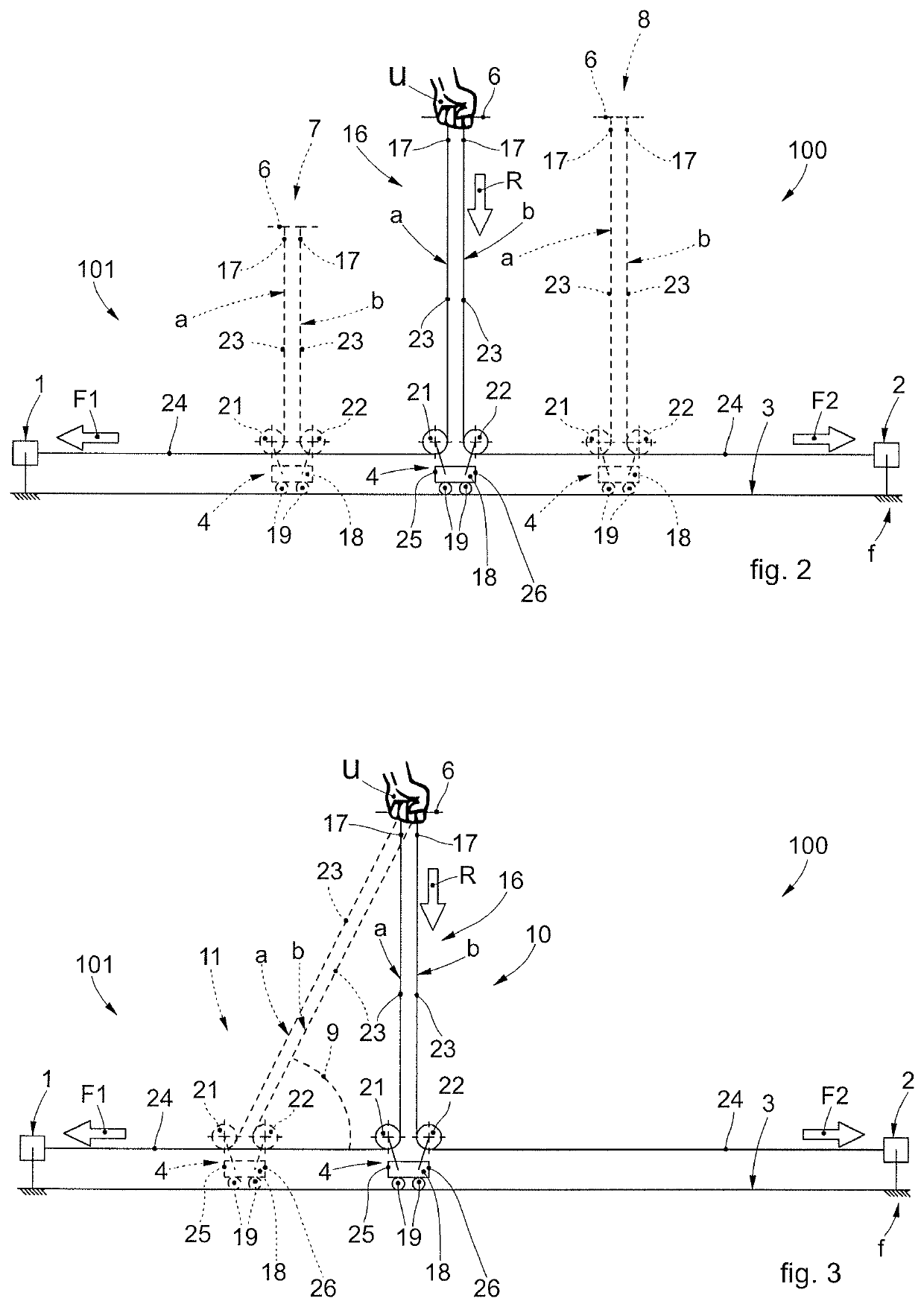
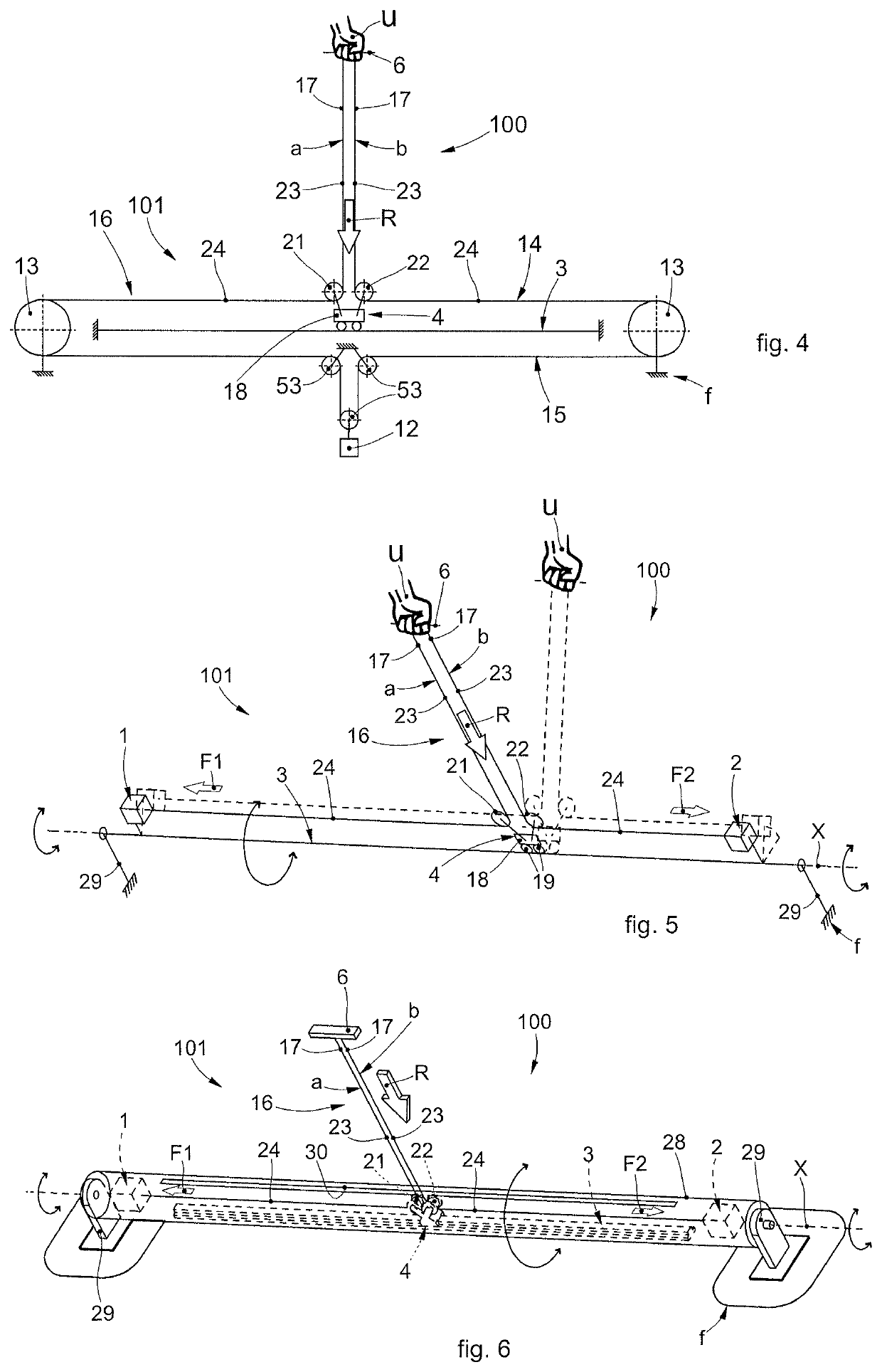
[0235]An exercise machine suitable for developing in a user U motor and functional abilities and muscular strength as well as for medical or rehabilitation purposes in which there is a machine frame f, p, grip elements 6 of a shape suitable for a body part, one or more cables a, b connected with the grip elements 6 and carrying resisting loads F, F1, F2 generated by load sources 1, 2 like weights stacks, resistance elements, pneumatic actuators or electric actuators. According to this embodiment the exercise machine comprises the machine frame f, p whereon a rail 3 is coupled for supporting a carriage 4 that slides along the rail and accommodates transmission means 5 that lead the cables a, b to the grip elements 6, one end of each cable being attached to the grip element 6 for a user's body part U and the other ends being connected with a respective load source 1, 2, the grip elements 6 being freely movable by the user U who perceives a resisting force R whose direction is substant...

embodiment 2

[0236]The exercise machine according to embodiment 1 wherein the load sources 1, 2 exert forces F1, F2 such as to make a resistance R to the user movements and to position the carriage 4 so that the angle 9 of the cables a, b is dependent substantially only on said forces F1, F2 and the carriage 4 follows the user's movements 12 to keep constant said angle 9, the user U being able to move freely, perceiving the resisting force R directed according to the angle 9.

embodiment 3

[0237]An exercise machine suitable for developing in a user motor and functional abilities and muscular strength as well as for medical or rehabilitation purposes which comprises a machine frame f, grip elements 6 of a shape suitable for a body part, one or more cables a, b connected with the grip elements 6 and carrying resisting loads F1, F2, generated by load sources 1, 2, like weights stacks, resistance elements, pneumatic actuators or electric actuators and characterized in that it comprises two resisting load sources 1, 2 acting on two cables a, b linked to the grip element 6, said resisting load sources exerting an amount of force F1, F2 such as to make a resistance to the user movements and to keep the angle of the resisting force R perceived at the grip element 6 at the desired value, the forces F1, F2 being dependent on the angles 9a, 9b of each cable a, b.


PUM


Abstract

Machine for gymnastic exercises comprising a sliding rail (3), a carriage (4) installed in a sliding manner on the sliding rail (3), a first pulley (21) and a second pulley (22) installed on the carriage (4) and rotatable in an idle manner around respective axes of rotation, a gripping element (6), cable traction means (16) comprising a first cable branch (a) and a second cable branch (b) provided with respective and separate connection ends (17) attached to the gripping element (6). The first cable branch (a) and the second cable branch (b) wind at least partly around the first pulley (21) and respectively the second pulley (22) to define first return segments (23) comprised between the gripping element (6) and respectively the first pulley (21) and second pulley (22), and second return segments (24) that extend one on a first side (25) and the other on a second side (26), opposite the first side (25), of the carriage (4) and substantially parallel to the sliding rail (3).

Description

CROSS-REFERENCE TO RELATED APPLICATION[0001]This application is a Section 371 of International Application No. PCT / EP2016 / 082035, filed Dec. 20, 2016, which was published in the English language on Aug. 10, 2017, under International Publication No. WO 2017 / 133823 A1, which claims priority under 35 U.S.C. § 119(b) to European Application No. 16425018.5, filed Feb. 3, 2016, the disclosures of which are incorporated herein by reference in their entirety.FIELD OF THE INVENTION[0002]The present invention relates to exercise machines suitable for developing motor and functional abilities, muscular strength and for medical or rehabilitation purposes. In particular, the present invention relates to an exercise machine in which the user acts on one or more grip elements each connected, through one or more cable traction means, to a resisting load source.BACKGROUND OF THE INVENTION[0003]Functional strength exercise machines are known for allowing a user to perform complex movements relatively...

Claims


Application Information

Patent Timeline
Patent Type & Authority Patents(United States)
IPC IPC(8): A63B21/00A63B21/062A63B24/00A63B71/00
CPCA63B21/156A63B21/154A63B24/0062A63B21/0628A63B21/4034A63B24/0087A63B21/4035A63B2220/16A63B2220/13A63B2024/0093A63B2071/0081A63B21/4043
Inventor CHIAVEGATO, MATTIARMANDOENGLARO, ALESSANDRO
Owner AKUIS SRL
Why Eureka
Try Eureka