
Artificial vision intraocular implant device

a technology of artificial vision and intraocular lens, which is applied in the field of ophthalmologic devices, can solve the problems of insufficient restoration or enhancement of inability of light to pass through the eye to the retina, and inability to properly restore the vision of patients with corneal conditions

Active Publication Date: 2020-04-21
SAINI MANJINDER
View PDF9 Cites 5 Cited by
  • Summary
  • Abstract
  • Description
  • Claims
  • Application Information

AI Technical Summary

Benefits of technology

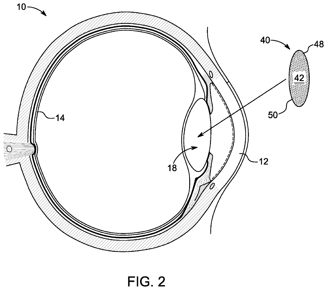
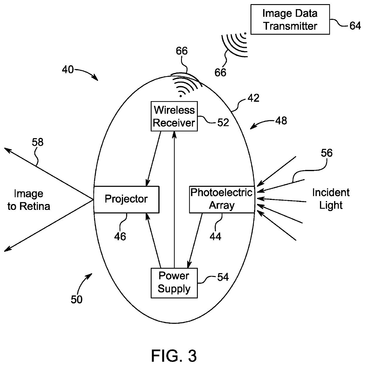
The present patent describes an intraocular photoelectric power supply system and an intraocular projection device for providing power to microelectronic devices implanted into the eye. The system includes an implant that is inserted into the lens chamber after a natural lens has been removed. The implant has photo-sensors that convert incident light into electricity, which can be used to power other electronics within the eye. The generated electricity can be stored in a battery or used immediately. The intraocular projection device includes a miniaturized projector that emits light patterns on the retina, which can be processed by the user's brain. The system also includes an external light source that irradiates a beam of light onto the photoelectric array on the implant. The technical effects of the patent include improved power supply and reduced size of the intraocular implant.

Problems solved by technology

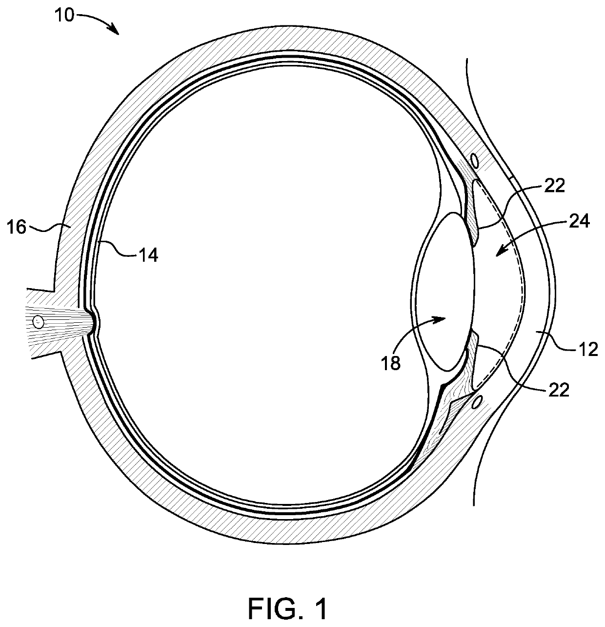
Many people experience impaired vision as a result of corneal dysfunction or damage, lens dysfunction or damage, or other conditions of the eye that lead to inability of light to properly pass through the eye to the retina.
However, such conventional procedures for replacing occluded or damaged lenses with replacement intraocular lens implants are often inadequate to restore or enhance vision of patients with corneal conditions.
As light initially enters the eye through the cornea, any conditions of the cornea which scatter or block light are generally not amenable to treatment via artificial lens replacement procedures.
Although many corneal replacement procedures do exist, they are often inadequate in improving or restoring sight.
Additionally, such procedures require extensive healing times and may cause other complications in the eye.

Method used


Image

  • Artificial vision intraocular implant device
  • Artificial vision intraocular implant device
  • Artificial vision intraocular implant device

Examples


first embodiment

[0065]Referring to FIG. 8a, a first embodiment divides the photoelectric collector array 44 into individual picture elements (pixels). Many digital cameras 64b use color filters in conjunction with each picture element to filter certain wavelengths of light out. Each picture element has an overlay of color filters, typically red, green, and blue, thus, when incident light 56 enters the apparatus, each picture element is able to measure the amount of light 56 entering in the red spectrum, the green spectrum, and the blue spectrum. In the power harnessing camera, a power aggregation layer may be positioned posterior each picture element or color energy measurement layer. The photoelectric element under each color filter may be optimized for the color or frequency of light for which the corresponding color filter is configured to measure, thus capturing the light energy that is activating the picture elements.

second embodiment

[0066]Referring to FIG. 8b, a second embodiment uses a similar system of capturing the chrominance by utilizing individual picture elements, however, color filters are substituted by prism 110 which separates the light into a spectrum. The subdivided light energy components (red, green, and blue) can be measured to determine the picture elements chrominance for each image cycle while all of the light energy can be harnessed by the photoelectric array positioned behind the prism. Thus, instead of filtering which reduces the total light and frequencies being received by each element of the photoelectric array, the full spectrum of incident light 56 may be collected.

third embodiment

[0067]Referring to FIG. 9, a third embodiment may utilize multilayer (multi-junction) photoelectric cells 120. The multi-junction photoelectric device may comprise layers of stacked photoelectric p-n junctions wherein each junction is receptive to a specific bandwidth of light frequencies and permits other bandwidths of light to pass through. A first layer comprises an incident light surface 124. An incident light surface 124 is selected to allow photons which have an energy level below a first specified frequency to pass through the incident light surface but captures photons having an energy level above the first specified frequency. A second layer 126, positioned below the incident light surface is selected to allow photons which have a second energy level below a second specified frequency to pass through the second layer, wherein the layer captures photons at a frequency between the first specified frequency and the second specified frequency. In this manner, a plurality of lay...


PUM


Abstract

An intraocular implant device for restoring, augmenting, or improving vision of a user, the implant including an intraocular implant body shaped for positioning inside a lens chamber of an eye, the body having an anterior side facing the cornea of the eye, and a posterior side facing the retina of the eye; a photoelectric sensor disposed on the anterior side of the body; wherein the photoelectric sensor is operable to receive incident light through the cornea and to convert the received light into electrical energy for use with one or more circuit components disposed on the body, and wherein the photoelectric sensor is nearly simultaneously operable to convert the received light into image data. The ocular implant device may include a projector for projecting the image data onto the retina of a user. The ocular implant may include a wireless receiver for receiving image data transmissions from an external source.

Description

CROSS-REFERENCES TO RELATED APPLICATIONS[0001]This application claims priority to and benefit of U.S. Provisional Application No. 62 / 517,894 filed Jun. 10, 2017 entitled INTRAOCULAR IMPLANT DEVICE, which is herein incorporated by reference in its entirety.[0002]A portion of the disclosure of this patent document contains material that is subject to copyright protection. The copyright owner has no objection to the reproduction of the patent document or the patent disclosure, as it appears in the U.S. Patent and Trademark Office patent file or records, but otherwise reserves all copyright rights whatsoever.STATEMENT REGARDING FEDERALLY SPONSORED RESEARCH OR DEVELOPMENT[0003]Not ApplicableREFERENCE TO SEQUENCE LISTING OR COMPUTER PROGRAM LISTING APPENDIX[0004]Not ApplicableBACKGROUND[0005]The present disclosure relates generally to ophthalmologic devices for implantation into the eye, and more particularly to intraocular implant devices and associated power supplies for enhancing or re...

Claims


Application Information

Patent Timeline
Patent Type & Authority Patents(United States)
IPC IPC(8): A61F9/08A61F2/16
CPCA61F9/08A61F2/1624A61F2250/0002
Inventor SAINI, MANJINDER
Owner SAINI MANJINDER
Learn More