Method and apparatus for identifying objects depicted in a videostream

a videostream and object technology, applied in image enhancement, signalling systems, instruments, etc., to achieve the effect of quick and accurate recognition, classification and positioning

Inactive Publication Date: 2006-08-15
GOOGLE LLC
View PDF19 Cites 545 Cited by
  • Summary
  • Abstract
  • Description
  • Claims
  • Application Information

AI Technical Summary

Benefits of technology

[0012]The method and apparatus of the present invention rapidly identifies, locates, and stores images of objects depicted in digitized image frames based upon one or more differentiable characteristic of the objects (e.g., versus non-objects and other detected background noise). The present invention may be implemented in a single microprocessor apparatus, within a single computer having multiple processors, among several locally-networked processors (i.e., an intranet), or via a global network of processors (i.e., the Internet and similar). Portions of individual image frames exhibiting an appreciable level of pre-selected differentiable characteristics of desired objects are extracted from a sequence of video data and said portions of the individual frames (and correlating data thereto) are used to confirm that a set of several “images” in fact represent a single “object” of a class of objects. These pre-selected differentiable characteristic criteria are chosen from among a wide variety of detectable characteristics including color characteristics (color-pairs and color set memberships), edge characteristics, symmetry, convexivity, lack of 3D volume, number and orientation of side edges, characteristic corner angles, frequency, and texture characteristics displayed by the 2-dimensional (2D) images so that said objects can be rapidly and accurately recognized. Preferably, the differentiable characteristics are chosen with regard to anticipated camera direction relative to anticipated object orientation so that needless processing overhead is avoided in attempting to extract features and characteristics likely not present in a given image frame set from a known camera orientation. Similarly, in the event that a scanning recording device, or devices, are utilized to record objects populating a landscape, area, or other space the extraction devices can be preferably applied only to those frames that likely will exhibit appreciable levels of an extracted feature or characteristic.
[0017]The present invention successfully handles partially obscured signs, skewed signs, poorly illuminated signs, signs only partially present in an image frame, bent signs, and ignores all other information present in the stream of digital frame data (preferably even the posts that support the signs). One of skill in the art will quickly recognize that the exemplary system described herein with respect to traffic control road signs is readily adaptable to other similar identification of a large variety of man-made structures. For example, cataloging the location, direction the camera is facing, condition, orientation and other attributes of objects such as power poles, telephone poles, roadways, railways, and even landmarks to assist navigation of vehicles can be successfully completed by implementing the inventive method described herein upon a series of images of said objects. In a general embodiment, the present invention can quickly and accurately distill arbitrary / artificial objects disposed in natural settings and except for confirming at least one characteristic of the object (e.g., color, linear shape, aspect ratio, etc.), the invention operates successfully without benefit of preexisting knowledge about the full shape, actual condition, or precise color of the actual object.
[0018]The present invention is best illustrated with reference to one or more preferred embodiments wherein a series of image frames (each containing a digital image of at least a portion of an object of interest) are received, at least two filters (or segmentation algorithms) applied, spectral data of the scene scrutinized so that those discrete images that exceed at least one threshold of one filter during extraction processing become the subject of more focused filtering over an area defined by the periphery of the image. The periphery area of the image is found by applying common region growing and merging techniques to grow common-color areas appearing within an object. The fuzzy logic color filter screens for the color presence and may be implemented as neural network. In either event, an image area exhibiting a peak value representative of a color set which strongly correlates to a road sign of interest is typically maintained for further processing. If and only if the color segmentation routine fails, a routine to determine the strength of the color pair output is then applied to each image frame that positively indicated presence of a color pair above the threshold noise level. Then, further segmentation is done possibly using color, edges, adaptive thresholding, color frequency signatures, or moment calculations. Preferably, the image frame is segmented into an arbitrary number of rectangular elements (e.g, 32 or 64 segments). The area where the color pair was detected is preferably grown to include adjacent image segments that also exhibit an appreciable color-pair signal in equal numbered segments. This slight expansion of a search space during the moment routine does not appreciably reduce system throughput in view of the additional confirming data derived by expanding the space. Morphology techniques are then preferably used to grow and erode the area defined by the moment routine-segmented space until either the grown representation meets or fails to meet uniform criteria during the dilation and erosion of the now segmented image portion of the potential object (“image”). If the image area meets the morphological criteria a final image periphery is calculated. Preferably, this final image periphery includes less than the maximum, final grown image so that potential sources of error, such as non-uniform edges, and other potentially complex pixel data are avoided and the final grown representation of the image essentially includes only the actual colored “face” of the road sign. A second order calculation can be completed using the basic segmented moment space which determines the “texture” of the imaged area—although the inventors of the present invention typically do not routinely sample for texture.
[0021]The frame buffer is typically generated by a digital image capture device. However, the present invention may be practiced in a system directly coupled to a digital image capture apparatus that is recording live images, or a pre-recorded set of images, or a series of still images, or a digitized version of an original analog image sequence. Thus, the present invention may be practiced in real time, near real time, or long after initial image acquisition. If the initial image acquisition is analog, it must be first digitized prior to subjecting the image frames to analysis in accordance with the invention herein described, taught, enabled, and claimed. Also a monitor can be coupled to the processing equipment used to implement the present invention so that manual intervention and / or verification can be used to increase the accuracy of the ultimate output, a synchronized database of characteristic type(s), location(s), number(s), damaged and / or missing objects.
[0024]Of course, certain characteristic colors themselves can assist the recognition of road signs from a scene. For example, a shade of yellow depicts road hazard warnings and advisories, white signs indicate speed and permitted lane change maneuver data, red signs indicate prohibited traffic activity, etc. Furthermore, since only a single font is approved for on-sign text messages in the U.S. character recognition techniques (e.g., OCR) can be applied to ensure accurate identification of traffic control signage as the objects of interest in a videostream. Therefore a neural network, as taught herein, is trained only on a few sets of image data including those visual characteristics of objects of interest such as color, reflectance, fluorescence, shape, and location with respect to a vehicle right of way operates to accurately identify the scenes in an economical and rapid manner. In addition, known line extracting algorithms, line completion, or “growing,” routines, and readily available morphology techniques may be used to enhance the recognition processing without adding significant additional processing overhead.
[0025]In a general application of the present invention, a conclusion may be drawn regarding whether object(s) appearing in a sequence of video data are fabricated by humans or naturally generated by other than manual processing. In this class of applications, the present invention can be applied to enhance the success of search and rescue missions where personnel and vehicles (or portions of vehicles) may be randomly distributed throughout a large area of “natural materials”. Likewise, the method taught in the present disclosure finds application in undersea, terrestrial, and extra-terrestrial investigations wherein certain “structured” foreign (artificial or man-made) materials are present in a scene of interest might only occur very infrequently over a very large sample of videostream (or similar) data. The present invention operates as an efficient graphic-based search engine too. The task of identifying and locating specific objects in huge amounts of video data such as searching for missile silos, tanks, or other potential threats depicted in images captured from remote sensing satellites or air vehicles readily benefits from the automated image processing techniques taught, enabled, and disclosed herein.

Problems solved by technology

This system also requires specific templates of real world features and does not operate on unknown video data with its inherent variability of lighting, scene composition, weather effects, and placement variation from said templates to actual conditions in the field.

Method used


Image

  • Method and apparatus for identifying objects depicted in a videostream
  • Method and apparatus for identifying objects depicted in a videostream
  • Method and apparatus for identifying objects depicted in a videostream

Examples


example 1

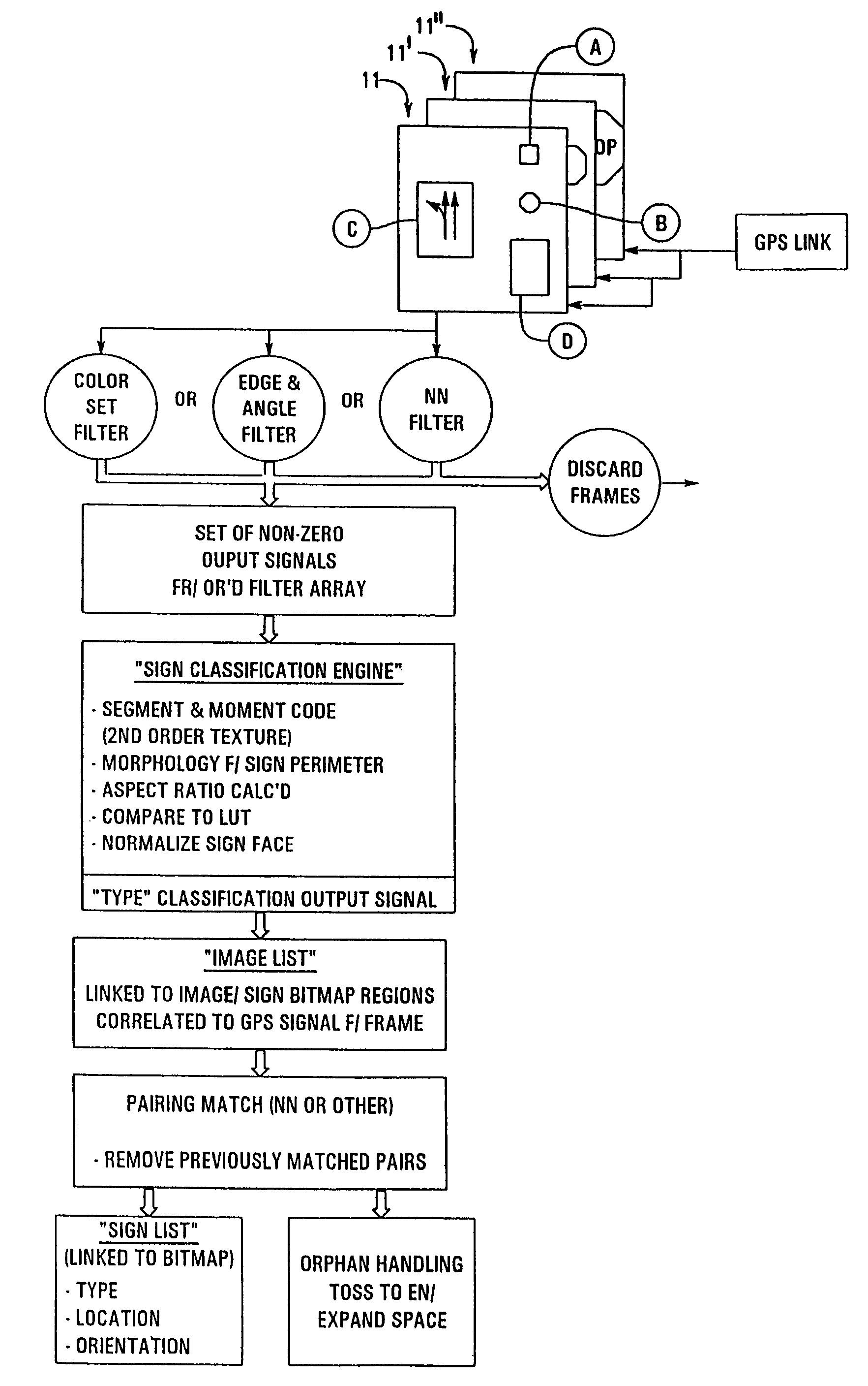
[0063]A method of recognizing and determining the location of at least one of a variety of road signs from at least two image frames depicting at least one road sign wherein available known values regarding the location, orientation, and focal length of an image capture device which originally recorded the at least two image frames, comprising the steps of:

[0064]receiving at least two image frames that each depict at least a single common road sign and which correspond to an identifier tag including at least a one of the following items: camera number, frame number, camera location coordinates, or camera orientation;

[0065]applying a fuzzy logic color filter to said at least two image frames;

[0066]filtering out and saving image frame portions containing each region that contain at least one pre-selected color-pair of a pair-set of approved road sign colors; and

[0067]saving to a memory location said image frame portions of the at least a single common road sign depicted in one of said...

example 2

[0068]An method for recognizing an object and classifying it by type, location, and visual condition from a digitized video segment of image frames comprising the steps of:

[0069]applying two filters to an image frame wherein the two filters each capture at least one differentiable characteristic of the object of interest;

[0070]extracting a first data set and a second data set from said two filters;

[0071]comparing said first data set and said second data set to threshold values;

[0072]discarding said image frame if the first or second data set do not exceed the threshold and

[0073]adding said image frame to an image frame library of possible images depicting actual objects.

example 3

[0074]A method for identifying similar objects depicted in at least two bitmap frame buffers of a digital processor, comprising the steps of:

[0075]receiving a digital image frame that corresponds to a unique camera, a camera location, an image frame reference value;

[0076]applying a set of equally weighted filters to said image frame wherein each of said equally weighted filters each creates an output signal adjusted to reflect the magnitude of a different differentiable characteristic of an object of interest;

[0077]OR-ing the resulting output signals from each of the equally weighted filters and saving only those image frames in which at least one of the equally weighted filters produces the output signal having a local maximum value.


PUM


Abstract

The present invention relates to an apparatus for rapidly analyzing frame(s) of digitized video data which may include objects of interest randomly distributed throughout the video data and wherein said objects are susceptible to detection, classification, and ultimately identification by filtering said video data for certain differentiable characteristics of said objects. The present invention may be practiced on pre-existing sequences of image data or may be integrated into an imaging device for real-time, dynamic, object identification, classification, logging / counting, cataloging, retention (with links to stored bitmaps of said object), retrieval, and the like. The present invention readily lends itself to the problem of automatic and semi-automatic cataloging of vast numbers of objects such as traffic control signs and utility poles disposed in myriad settings. When used in conjunction with navigational or positional inputs, such as GPS, an output from the inventative systems indicates the identity of each object, calculates object location, classifies each object by type, extracts legible text appearing on a surface of the object (if any), and stores a visual representation of the object in a form dictated by the end user / operator of the system. The output lends itself to examination and extraction of scene detail, which cannot practically be successfully accomplished with just human viewers operating video equipment, although human intervention can still be used to help judge and confirm a variety of classifications of certain instances and for types of identified objects.

Description

RELATED APPLICATIONS[0001]The present application is a continuation of application Ser. No. 10 / 244,318, filed Sep. 16, 2002 now U.S. Pat. No. 6,625,315, entitled, “METHOD AND APPARATUS FOR IDENTIFYING OBJECTS DEPICTED IN A VIDEOSTREAM,” which is a continuation of application Ser. No. 09 / 177,836, filed Oct. 23, 1998 entitled, “METHOD AND APPARATUS FOR IDENTIFYING OBJECTS DEPICTED IN A VIDEOSTREAM,” now U.S. Pat. No. 6,266,442, and a continuation of application Ser. No. 09 / 812,753 filed Mar. 20, 2001 now U.S. Pat. No. 6,453,056, entitled, “METHOD AND APPARATUS FOR GENERATING A DATABASE OF ROAD SIGN IMAGES AND POSITIONS,” the disclosures of both are hereby incorporated by reference.FIELD OF THE INVENTION[0002]The present invention relates generally to the field of automated image identification. In particular, identification of objects depicted in one ore more image frames of segment of video. The present invention teaches methods for rapidly scrutinizing digitized image frames and cla...

Claims


Application Information

Patent Timeline
Patent Type & Authority Patents(United States)
IPC IPC(8): G06K9/00G06K9/46G06T5/00G06T7/00
CPCG06K9/00818G06K9/4609G06T7/0081G06T7/0044G06T2207/30252G06T2207/10016G06T7/74G06T7/11G06V20/582G06V10/443
Inventor LAUMEYER, ROBERT ANTHONYRETTERATH, JAMES EUGENE
Owner GOOGLE LLC
Why Eureka
Try Eureka