Three-dimensional imaging and display system

a display system and three-dimensional imaging technology, applied in the field of three-dimensional imaging and display systems, can solve the problems of inordinate difficulty in measuring at short distances, high equipment cost and complexity, and inconvenient use,

Active Publication Date: 2011-09-13
APPLE INC
View PDF20 Cites 570 Cited by
  • Summary
  • Abstract
  • Description
  • Claims
  • Application Information

AI Technical Summary

Problems solved by technology

In 3D, however, such constructs can be indirect, time consuming, artificial, and can require considerable practice and training to do well.
Measurements at short distances can be inordinately difficult.
Equipment costs and complexity are correspondingly high, making TOF unattractive for ordinary consumer applications.
The difficulty with the light attenuation technique, however, is that different objects are more or less reflective, so the measurement is very dependent upon the reflectivity of the target object.
Both techniques, however, are inconvenient and unnecessarily complicated, as well as costly.
A need thus remains for uncomplicated, economical, yet highly effective 3D input devices for computers.
Solutions to these problems have been long sought but prior developments have not taught or suggested any solutions and, thus, solutions to these problems have long eluded those skilled in the art.

Method used


Image

  • Three-dimensional imaging and display system
  • Three-dimensional imaging and display system
  • Three-dimensional imaging and display system

Examples


Embodiment Construction

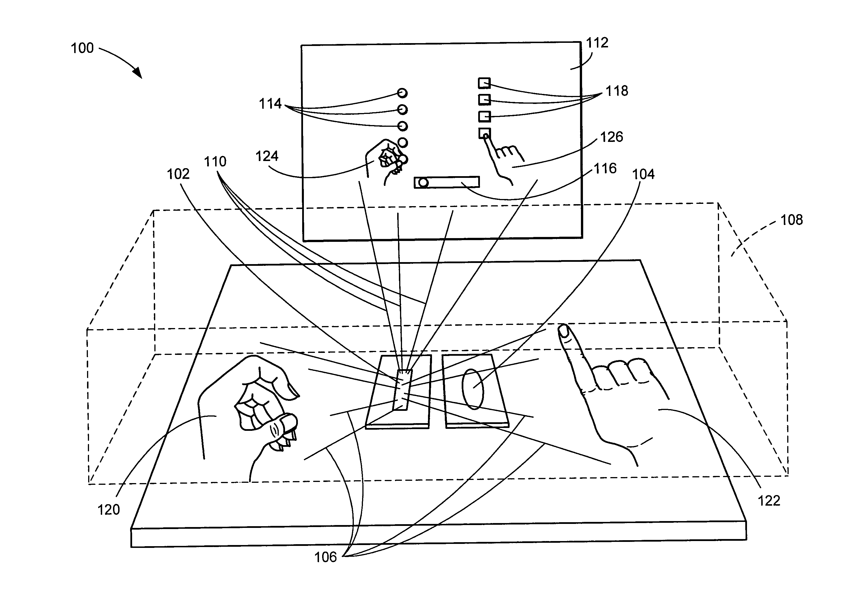
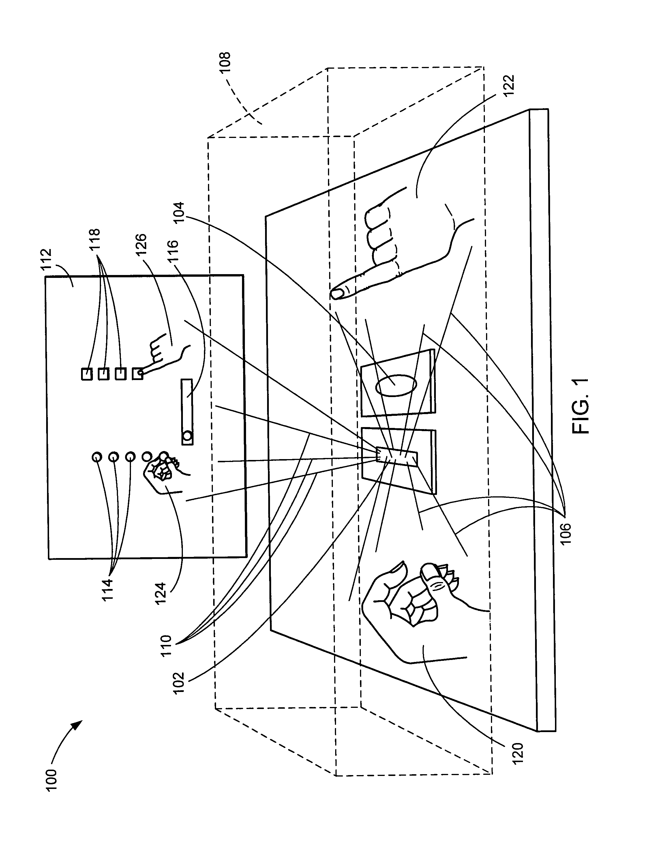
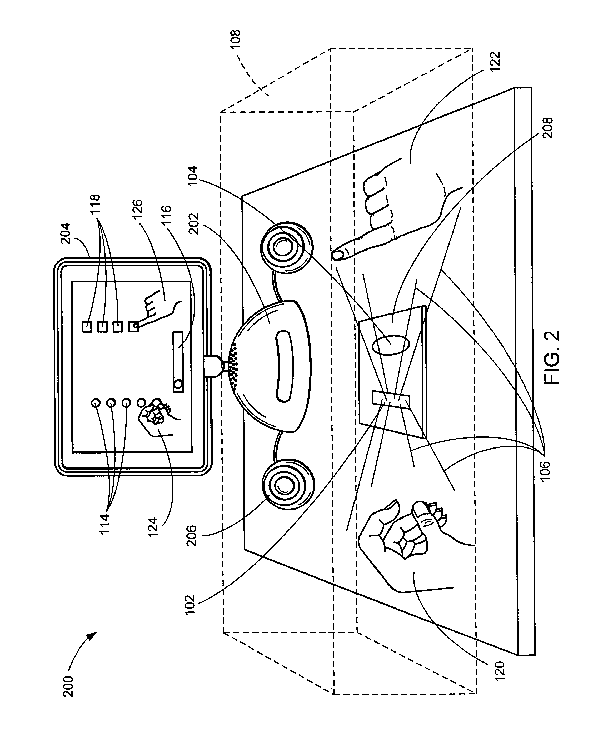
[0024]The following embodiments are described in sufficient detail to enable those skilled in the art to make and use the invention. It is to be understood that other embodiments would be evident based on the present disclosure, and that process or mechanical changes may be made without departing from the scope of the present invention.

[0025]In the following description, numerous specific details are given to provide a thorough understanding of the invention. However, it will be apparent that the invention may be practiced without these specific details. In order to avoid obscuring the present invention, some well-known circuits, system configurations, and operational steps are not disclosed in detail.

[0026]Likewise, the drawings showing embodiments of the device are semi-diagrammatic and not to scale and, particularly, some of the dimensions are for the clarity of presentation and are shown greatly exaggerated in the drawing FIGs.

[0027]Similarly, the views in the drawings, for ease...


PUM


Abstract

A three-dimensional imaging and display system is provided in which user input is optically detected in an imaging volume by measuring the path length of an amplitude modulated scanning beam as a function of the phase shift thereof. Visual image user feedback concerning the detected user input is presented.

Description

TECHNICAL FIELD[0001]The present invention relates generally to imaging, and more particularly to a three-dimensional imaging and display system.BACKGROUND ART[0002]Modern three-dimensional (“3D”) imaging and display technologies are employed in widely diverse environments and technologies. Examples include medical diagnostics, entertainment, flight simulation, robotics, education, animation, biomechanical studies, virtual reality, and so forth. There are numerous 3D input devices including, for example, variations on the computer mouse or touch pad. Ordinarily, these are manipulated in just two dimensions, the x-axis and the y-axis. However, through various computer programming artifices, these devices can provide a measure of control in the third dimension of the z-axis. In 3D, however, such constructs can be indirect, time consuming, artificial, and can require considerable practice and training to do well. Similar observations can be made relative to joysticks, which in their or...

Claims


Application Information

Patent Timeline
Patent Type & Authority Patents(United States)
IPC IPC(8): G01C3/08G01S7/4861G01S7/4865G01S17/14
CPCG01B11/00G06F3/04886G06F3/012G06F3/017G06F3/0325G01C3/085G01S17/36G01S17/48G01S7/4817G01S7/4861G01S7/4865G01S17/66G06F3/011G06F3/02G06F3/04815G06F3/005G01C3/12G01S17/105G01S17/14
Inventor KRAH, CHRISTOPH H.
Owner APPLE INC
Why Eureka
Try Eureka