Ball throwing assistant

a ball throwing assistant and ball throwing technology, applied in the direction of launching weapons, gymnastic exercise, sport apparatus, etc., can solve the problems of cumbersome triggering of the machine to throw a ball and manual change of variable settings

Inactive Publication Date: 2003-04-01
KONINK PHILIPS ELECTRONICS NV
View PDF8 Cites 575 Cited by
  • Summary
  • Abstract
  • Description
  • Claims
  • Application Information

AI Technical Summary

Problems solved by technology

First, triggering the machine to throw a ball is cumbersome.
A second disadvantage is that variable settings must be changed manually.

Method used


Image

  • Ball throwing assistant
  • Ball throwing assistant
  • Ball throwing assistant

Examples


Embodiment Construction

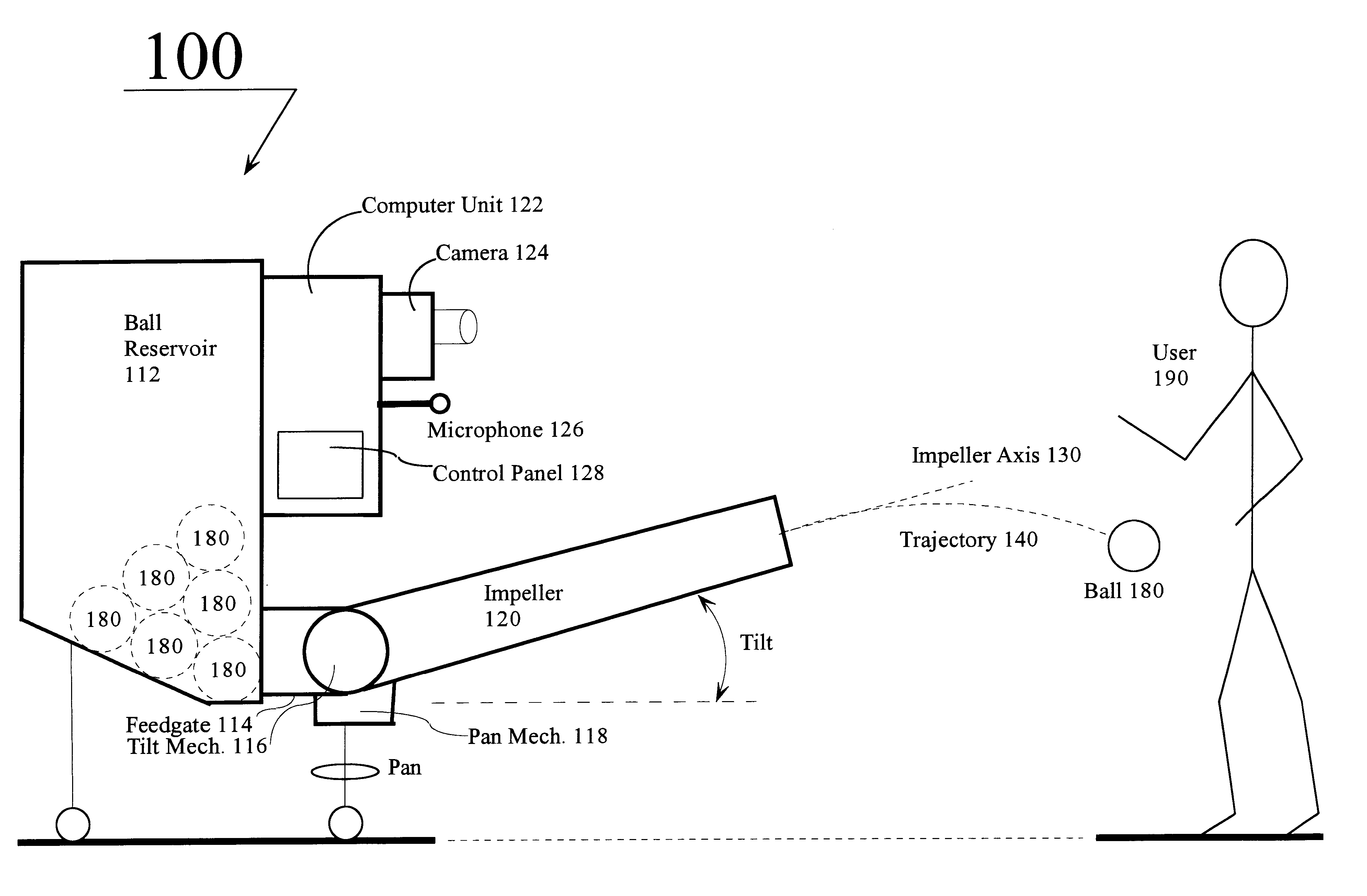
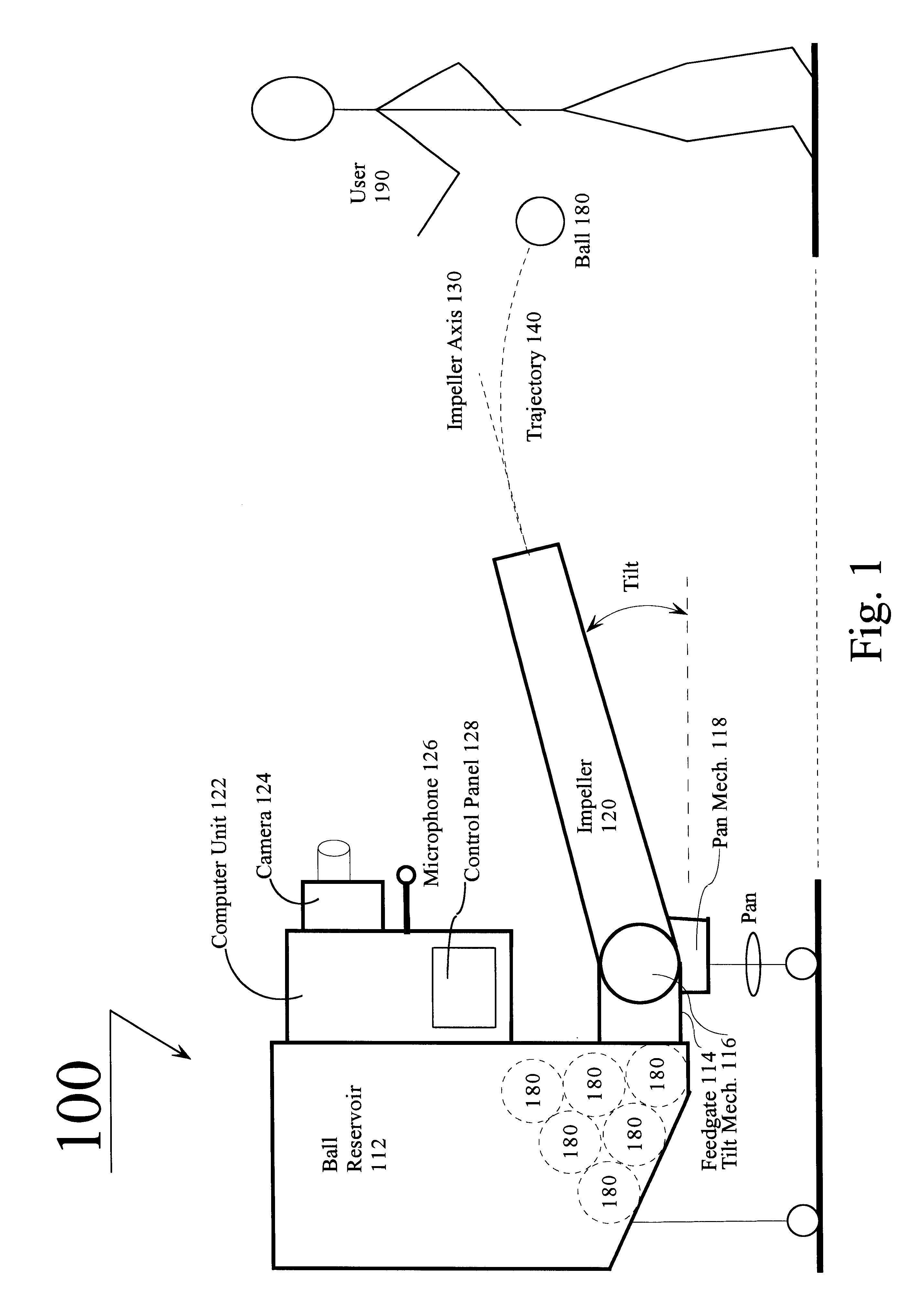
FIG. 1 depicts a possible physical appearance of a ball-throwing machine 100 in accordance with the present invention. Balls 180 to be projected are loaded into ball reservoir 112, from which they reach feedgate 114. A method as simple as gravity can be used to route the balls 180 into feedgate 114, and the geometry of feedgate 114 can be arranged such that only a single ball 180 may enter it at any one time. Activation of feedgate 114 introduces a ball 180 into impeller 120, which projects the ball 180 along impeller axis 130 toward a user 190. The general orientation of ball-throwing machine 100 establishes a direction in which the ball 180 is propelled. Adjustments in the direction may be effected by activating pan mechanism 118, which alters the angle of impeller axis 130 in a horizontal plane. Adjustments in the vertical angle of impeller axis 130 may by effected by activating tilt mechanism 116. A control panel 128 has manual controls which may be used to turn ball-throwing ma...


PUM


Abstract

A ball-throwing machine includes a camera connected to a computer vision unit and a microphone connected to a speech-processing unit. The computer vision unit processes images from the camera to determine a user's position, and to detect user gestures from a predetermined repertoire of gestures. The speech-processing unit recognizes user vocal commands from a predetermined repertoire of commands. A computer receives information from a control panel, from the computer vision unit, from the speech-processing unit, and from a file describing the ballistic properties of the ball to be thrown. The computer accordingly determines a ball trajectory according to the user's position and parameters indicated by a combination of control-panel settings, user gestures, and user vocal commands. The computer then adjusts the direction, elevation, ball speed, and ball spin to conform to the determined trajectory, and initiates throwing of a ball accordingly.

Description

1. Field of the InventionThis invention relates to an apparatus and method for controlling the operation of a ball-throwing machine.2. Description of the Related ArtThere are many kinds of automatic ball throwing machines, intended to aid sports practice for players of ball-oriented sports. These machines automatically throw balls in a desired direction to allow people to train, practice, and build skills at playing various kinds of sports. For example, a softball throwing machine like pitching machines from The Jugs Company.RTM. throws softballs or baseballs. One can set the pitching machines to throw a particular type of pitch selected from a variety of predefined pitch types, such as fastballs, curveballs, sliders, etc., and some of the machines offer the option of making various adjustments that can be made to the speed at which the pitches are thrown, the angle at which they are thrown, whether they are thrown to simulate throwing by a left-handed or a right-handed pitcher.Simi...

Claims


Application Information

Patent Timeline
Patent Type & Authority Patents(United States)
IPC IPC(8): A63B24/00A63B65/00A63B65/12A63B69/40A63B69/00
CPCA63B24/00A63B24/0021A63B65/12A63B69/40A63B69/406A63B2225/50A63B2069/0008A63B2069/402A63B2071/068A63B2220/807A63B2024/0028
Inventor TRAJKOVIC, MIROSLAVCOHEN-SOLAL, ERICGUTTA, SRINIVAS
Owner KONINK PHILIPS ELECTRONICS NV
Why Eureka
Try Eureka