Spindle unit for turning and milling machines

a technology for turning milling machines and spindles, which is applied in driving apparatuses, maintenance and safety accessories, measurement/indication equipment, etc., can solve the problems of increasing the danger of collision with surrounding parts or other aggregates of machines, requiring a bit of working space, and relatively long construction lengths. achieve the effect of simple and compa

Active Publication Date: 2020-04-21
GILDEMEISTER DREHMASCHEN
View PDF23 Cites 0 Cited by
  • Summary
  • Abstract
  • Description
  • Claims
  • Application Information

AI Technical Summary

Benefits of technology

[0009]Some exemplary embodiments are based on the object to provide a tool motor spindle presenting a construction which is as simplified and compact as possible.

Problems solved by technology

Both embodiments have the disadvantage that their construction length is relatively long and, therefore, they need some space in the working space of turning and milling machines.
Further, the danger of collisions with surrounding parts or other aggregates of the machine increases, especially in machine tools having a pivotable spindle unit.
However, such clamping cylinders which are integrated into the shaft present complexly configured rotational bushings which have to transfer three fluids in order to introduce the cooling agent and to introduce the hydraulic driving.

Method used


Image

  • Spindle unit for turning and milling machines

Examples


Embodiment Construction

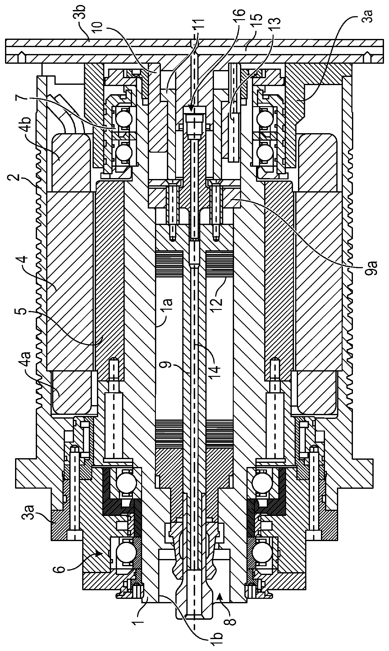
[0013]The object mentioned above is achieved in the spindle unit by the fact that at least a segment of the non-rotating ring cylinder is received in a rear end portion of the working spindle. According to the invention a sensor for detecting the position of said tie rod is arranged in the zone of this segment.

[0014]Here, the approach is based on the principle to integrate the construction of said ring cylinder as far as possible into the open bore of the rear end portion of said working spindle. Here, according to the invention only non-rotating ring cylinders which as such are already known are employed. In this manner the basic construction of the motor spindle may be kept simple while at the same time a highly compact construction may be achieved.

[0015]A special advantage of the spindle unit results from the inventive arrangement of said sensor for detecting the position of said tie rod of said releasing device in the zone of the non-rotating part, however, within said working s...


PUM

PropertyMeasurementUnit
tensionaaaaaaaaaa
lengthaaaaaaaaaa
outer dimensionsaaaaaaaaaa

Abstract

A spindle unit for machine tools that includes a working spindle rotationally bearing-mounted in axially spaced spindle bearings in a spindle case, and an electric driving motor. The working spindle includes at its head side a clamping device for a tool and at its rear side a non-rotating ring cylinder for activating said clamping device via a rotating tie rod, and rotational bushing for supplying said tool with cooling and / or lubricating agents through a hydraulic conduit extending longitudinally through said working spindle. At least a segment of the non-rotating ring cylinder may be received in the rear end portion of said working spindle.

Description

CROSS REFERENCES TO RELATED APPLICATIONS[0001]This application claims the benefit of European Patent Application No. 13195734.2, filed Dec. 4, 2013, which is hereby incorporated by reference herein in its entirety.FIELD OF INVENTION[0002]The invention relates to a spindle unit for machine tools comprising a working spindle rotationally bearing-mounted in a spindle case and an electric driving motor.BACKGROUND[0003]Such a spindle is, for example, known from EP 14 09 197 B1 in which a tie rod loaded at one side by a spring package is arranged in a continuous bore, said tie rod comprising at its one end a clamping head with which the tool can be retracted in a clamping cone of said tool spindle. In order to supply the tools with lubricating or cooling means, the tie rod itself comprises a longitudinal bore to which a non-rotating conduit is coupled via a rotational bushing. The work piece spindle is rotationally bearing-mounted in the direction of the rotating axis in front of and behi...

Claims


Application Information

Patent Timeline
Patent Type & Authority Patents(United States)
IPC IPC(8): B23Q5/10B23Q11/10B23Q17/00B23B31/26B23B31/12
CPCB23Q17/003B23B31/1261B23B31/265B23Q5/10B23Q11/1015Y10T409/309464B23B31/261
Inventor HALM, CHRISTIANLAXY, ROBERT
Owner GILDEMEISTER DREHMASCHEN
Why Eureka
Try Eureka