Compression device

a compression device and gas flow technology, applied in the direction of refrigeration components, machines/engines, lighting and heating apparatus, etc., can solve the problems of heat energy, which is to be effectively recovered in the energy recovery system, may decrease, and the pressure loss of compressed gas in the flow passage may increase, so as to reduce the pressure loss of compressed gas and the effect of effective heat energy recovery

Active Publication Date: 2020-04-21
KOBE STEEL LTD
View PDF19 Cites 1 Cited by
  • Summary
  • Abstract
  • Description
  • Claims
  • Application Information

AI Technical Summary

Benefits of technology

[0005]An object of the present invention is to provide a compression device that can achieve an effective recovery of heat energy included in compressed gas and a reduction of a pressure loss of the compressed gas.

Problems solved by technology

However, since the evaporator is provided, a pressure loss of the compressed gas in a flow passage may increase.
As a result, heat energy, which is to be effectively recovered in the energy recovery system may decrease.

Method used


Image

  • Compression device
  • Compression device
  • Compression device

Examples


Embodiment Construction

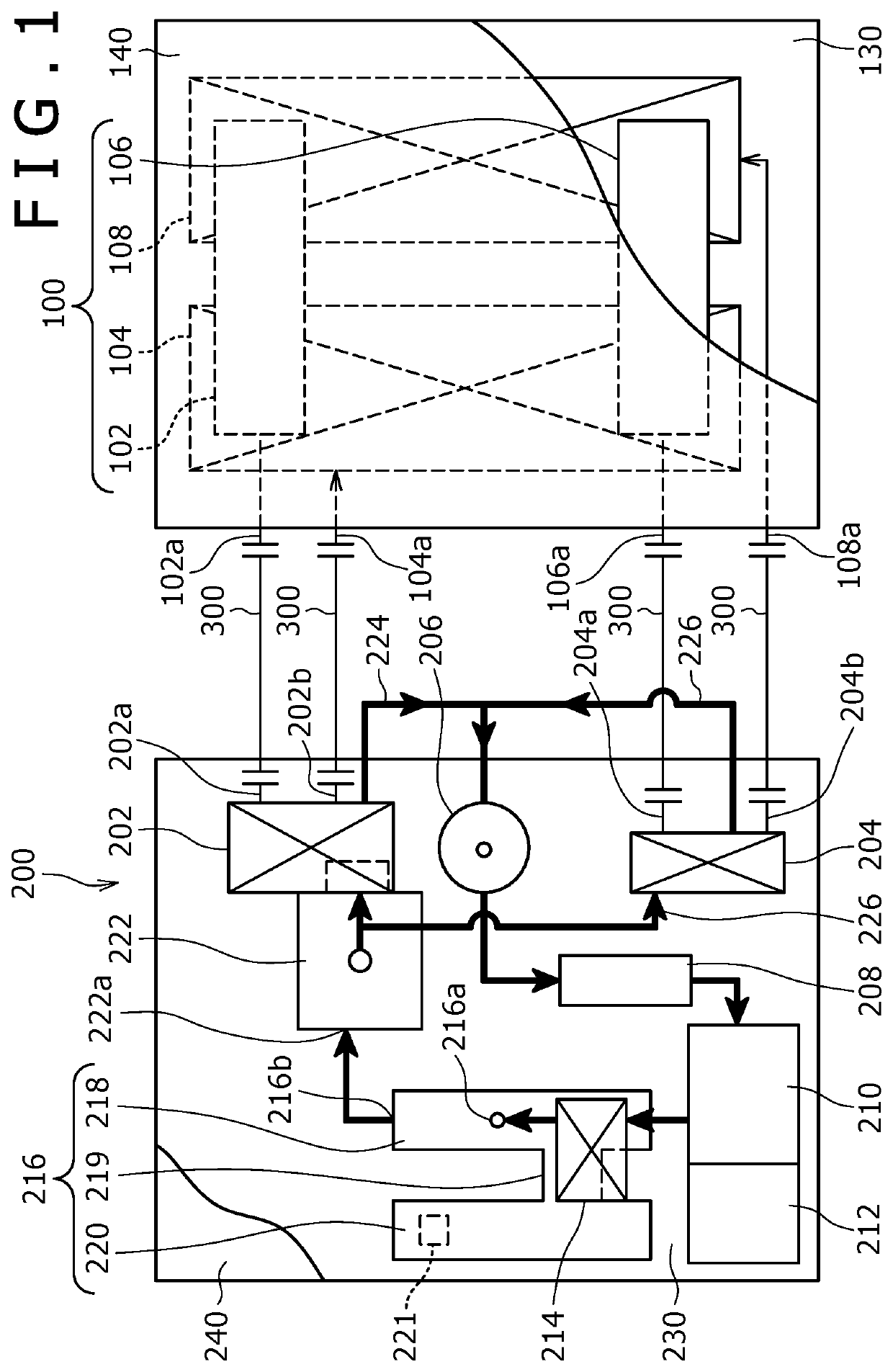
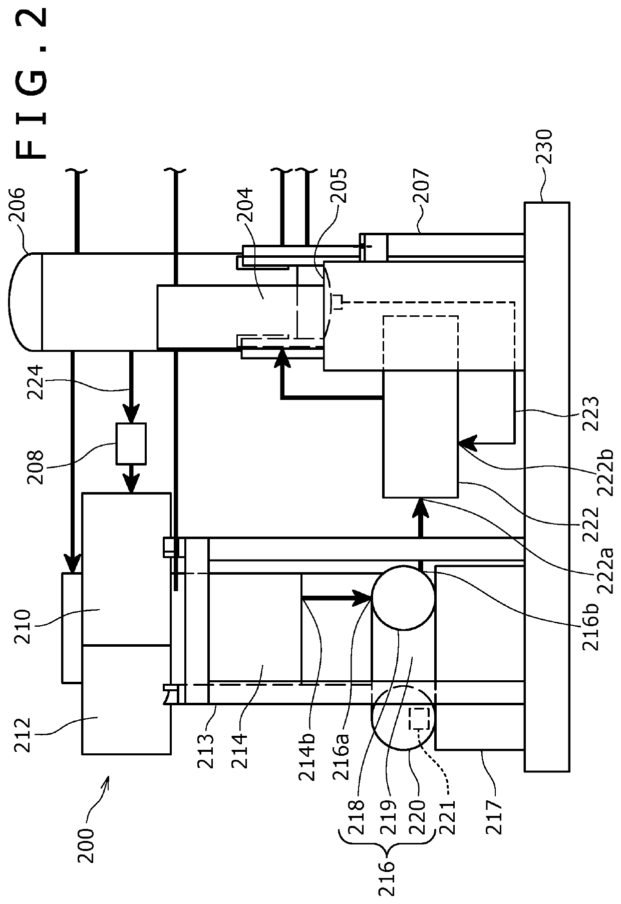
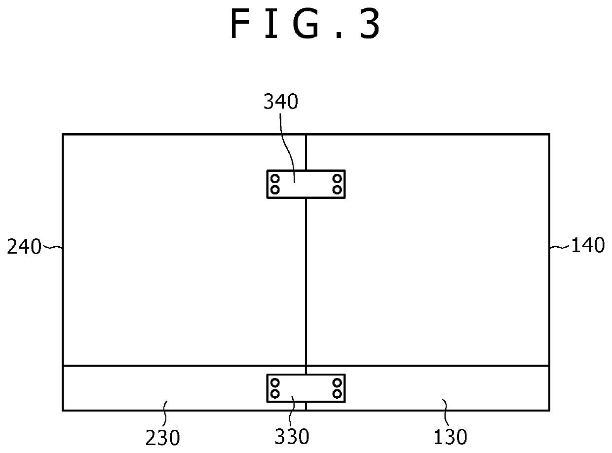
[0017]A compression device according to an embodiment of the present invention will be described with reference to FIG. 1 to FIG. 3.

[0018]As shown in FIG. 1, the compression device includes a compression device body 100 and a heat energy recovery unit 200.

[0019]The compression device body 100 includes a first compressor 102 for compressing gas (for example, air), a first cooler 104, a second compressor 106 for further compressing the compressed gas that has flowed out from the first cooler 104, and a second cooler 108.

[0020]The first compressor 102 is a screw compressor. Specifically, the first compressor 102 includes a compressor body, a motor, and a power transmission device for transmitting power of the motor to the compressor body. The compressor body includes a screw rotor, a housing that houses the screw rotor, and a discharge section for discharging the compressed gas. The screw rotor is formed by a rotor shaft as a rotary shaft and a screw (compression member) that is rotata...


PUM


Abstract

A compression device is equipped with a compressor (102) and a heat energy recovery unit (200) that recovers heat energy from a compressed gas. The heat energy recovery unit (200) is equipped with: a heat exchanger (202) that has an inflow port (202a), and that heats an operating medium by means of the heat from the compressed gas; an expansion device (210); a power recovery unit (212); a condenser (214); and a pump (222). The heat exchanger (202) is arranged closer to the compressor (102) than the expansion device (210), and is oriented such that the inflow port (202a) faces the compressor (102).

Description

TECHNICAL FIELD[0001]The present invention relates to a compression device.BACKGROUND ART[0002]A system for recovering heat energy included in compressed gas that has been discharged from a compressor has been recently proposed. For example, Patent Document 1 discloses an energy recovery system of a compression device including: a compressor; an evaporator for conducting heat exchange between compressed gas that has been discharged from the compressor and a liquid-phase working medium; a cooler for cooling the gas that has flowed out from the evaporator; a turbine in which the gas-phase working medium that has flowed out from the evaporator flows; an AC generator connected to the turbine; a condenser for condensing the working medium that has flowed out from the turbine; and a circulating pump for pumping the liquid-phase working medium that has flowed out from the condenser, to the evaporator. In this system, energy included in the compressed gas is recovered in the evaporator and ...

Claims


Application Information

Patent Timeline
Patent Type & Authority Patents(United States)
IPC IPC(8): F25B25/00F01K23/08F25B11/02F25B9/06
CPCF25B11/02F01K23/08F25B2500/01F25B25/005F25B9/06F01C1/00F01K27/02
Inventor HASHIMOTO, KOICHIRONISHIMURA, KAZUMASAADACHI, SHIGETONARUKAWA, YUTAKAMATSUDA, HARUYUKIKAKIUCHI, TETSUYATSUBOI, NOBORUFUKUHARA, KAZUNORI
Owner KOBE STEEL LTD
Why Eureka
Try Eureka