Clamping system with controlled angular positioning for connecting together two tubes

a technology of angular positioning and clamping system, which is applied in the direction of flanged joints, pipe joints, sleeves/socket joints, etc., can solve the problems of lengthening the process of assembling the tubes together, and achieve the effect of reducing the deflection of the blocking tab, facilitating co-operation, and increasing the flexibility of the blocking tab

Active Publication Date: 2020-04-28
ESTAB CAILLAU SARL
View PDF19 Cites 3 Cited by
  • Summary
  • Abstract
  • Description
  • Claims
  • Application Information

AI Technical Summary

Benefits of technology

[0010]Thus, the co-operation between the blocking element and the positioning member ensures that the clamping system and the first tube are arranged angularly relative to each other in the desired manner. This angular position may be predetermined by the respective locations selected for the blocking element on the washer and for the positioning element on the first tube. In addition, the co-operation between the blocking element and the positioning member serves to avoid having recourse to a third part such as a retaining tab, thereby limiting the complexity of the clamping system. Furthermore, insofar as the angular position is controlled by the washer co-operating with the first tube, no additional space is occupied outside said tube, unlike the system proposed in WO 2016 / 034820.
[0030]Optionally, the first tube has a radial projection, and the positioning member extends as far as the radial projection. Thus, the co-operation between the positioning member and the blocking element does not prevent the washer from coming against the radial projection and thus providing good sealing.

Problems solved by technology

Nevertheless, it occupies additional space outside the first tube and needs to be attached to the first tube during an additional step, e.g. a welding step, thereby lengthening the process of assembling the tubes together.

Method used


Image

  • Clamping system with controlled angular positioning for connecting together two tubes
  • Clamping system with controlled angular positioning for connecting together two tubes
  • Clamping system with controlled angular positioning for connecting together two tubes

Examples


Embodiment Construction

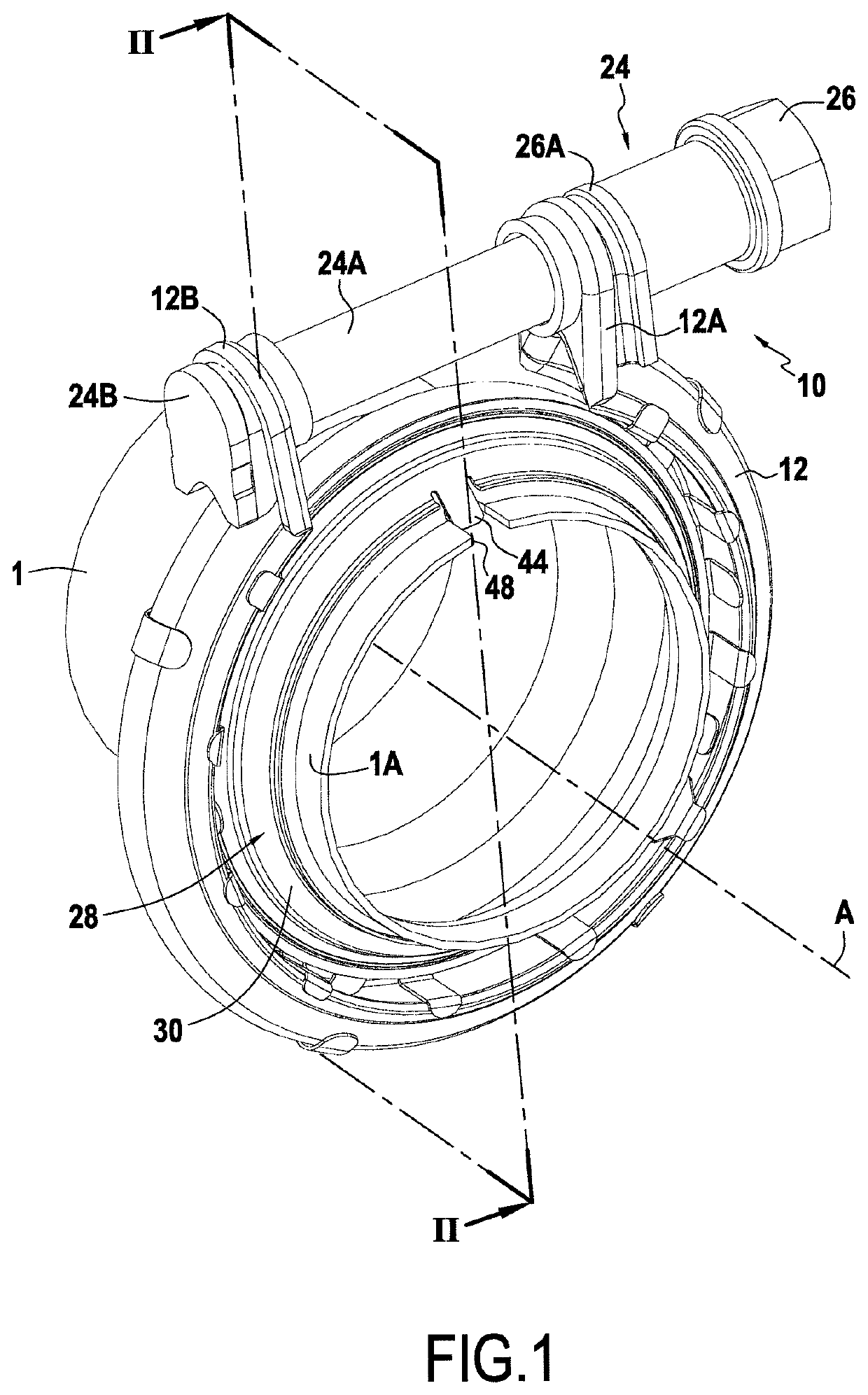
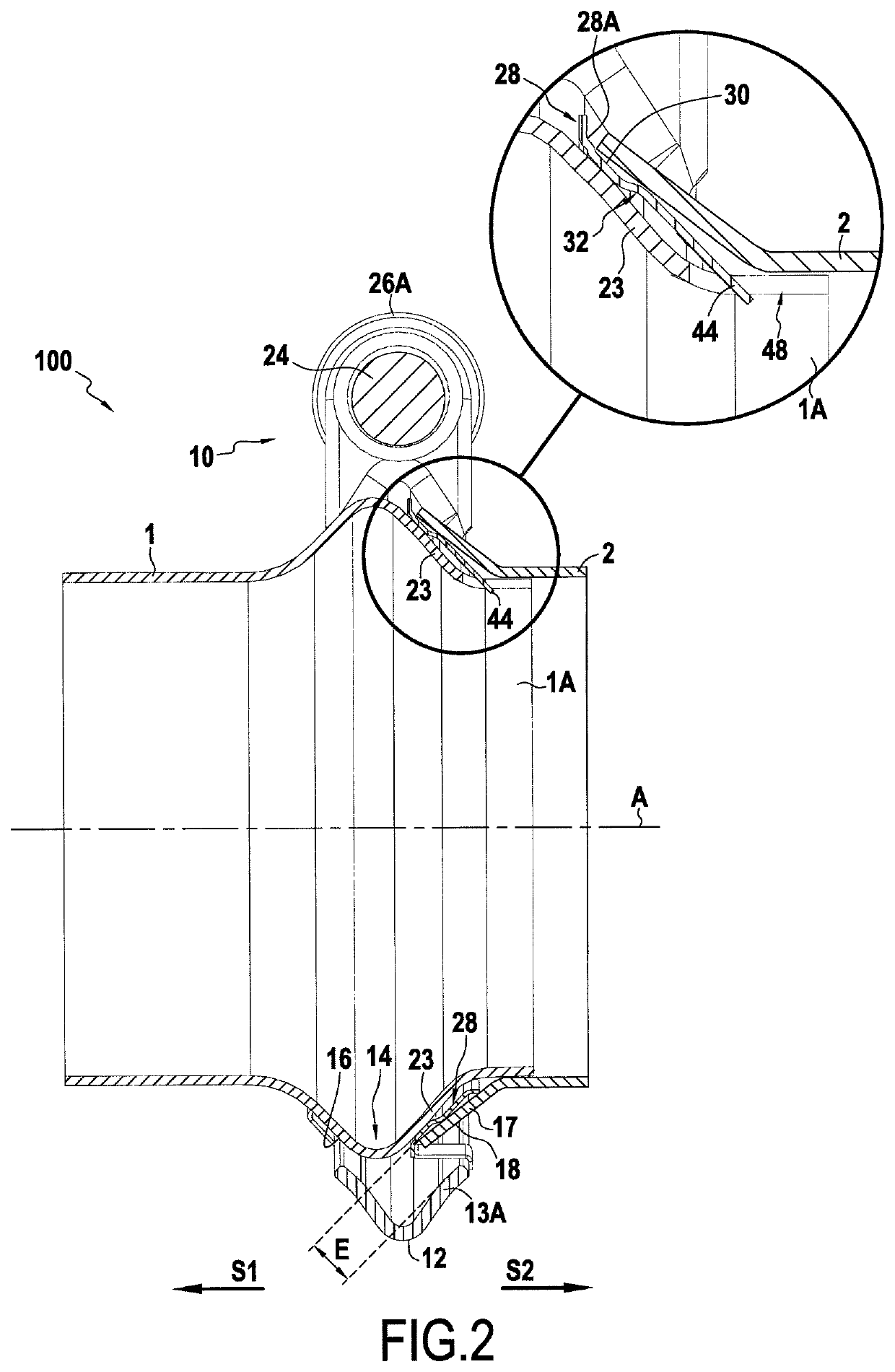
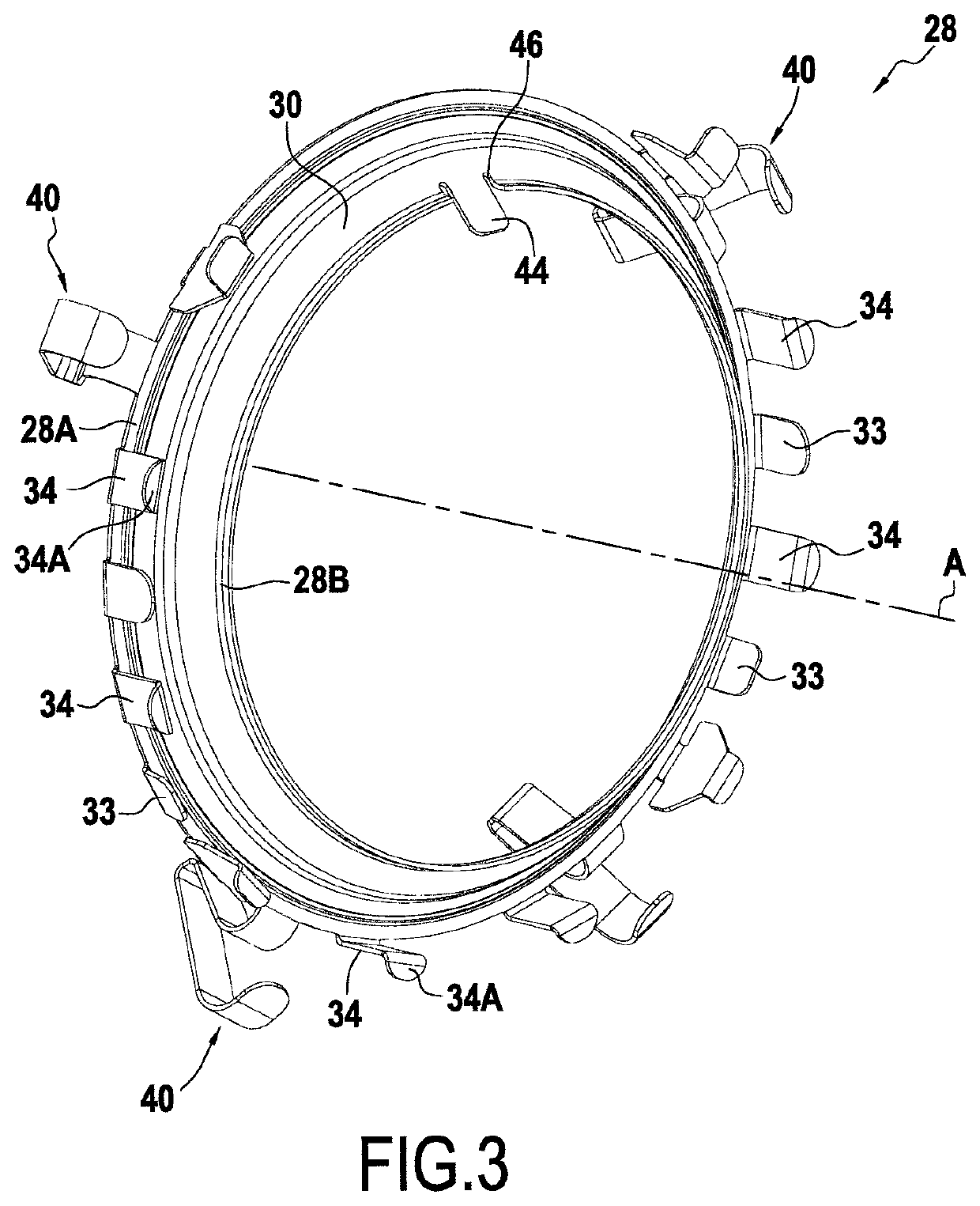
[0040]The description begins with FIGS. 1 to 3. In these figures, it can be seen that the clamping system comprises a collar 10, generally of the same type as that described in EP 1 451 498 and WO 2012 / 013891, and a washer 28, that co-operate to assemble together two tubes 1 and 2. It should nevertheless be understood that the invention is not limited to this type of collar.

[0041]As mentioned above, the term “inner” is used to designate elements that face towards the axis A of the two tubes placed end to end or that are closer to the axis A relative to other elements that are said to be “outer”, the “outer” elements also being elements that face away from the axis A.

[0042]Specifically, and as can be seen in FIGS. 1 and 2, the collar comprises a band 12 that has an inner periphery that defines a setback 14 in which it is possible to insert bearing surfaces, respectively a bearing surface 16 forming part of the first tube 1 and a bearing surface 18 forming part of the second tube 2. T...


PUM


Abstract

A system for connecting a first tube (1) and a second tube, the system comprising a clamping collar (10) suitable for being tightened around the abutted ends of the two tubes, and a washer (28) secured to the clamping collar by securing means. The washer (28) presents a blocking element (44) configured to co-operate with a corresponding positioning member (48) of the first tube (1) so as to block the washer (28) against turning relative to the first tube (1).

Description

CLAIM OF PRIORITY[0001]This application claims priority from French Patent Application No. FR 1659571, filed on Oct. 4, 2016, and is incorporated herein by reference in its entirety.BACKGROUND OF THE DISCLOSURE[0002]The present invention relates to a system for connecting together a first tube and a second tube, the system comprising a clamping collar suitable for being tightened around the abutted ends of the two tubes, and a washer secured to the clamping collar by securing means.[0003]A clamping system of this type is known from European patent EP 1 451 498. In that patent, the facing tube ends present bearing surfaces that project relative to the cylindrical outside surfaces of said tubes. The clamping collar comprises a clamping band of section that may for example be substantially V-shaped or U-shaped, so that the branches formed by that section bear respectively against the bearing surface of the first tube and against the bearing surface of the second tube. Thus, tightening ...

Claims


Application Information

Patent Timeline
Patent Type & Authority Patents(United States)
IPC IPC(8): F16L23/08F16L23/20F16L19/02F16L23/16
CPCF16L23/08F16L19/0206F16L23/162F16L23/20F16L21/08F16L21/065F16L21/00
Inventor RIGOLLET, NICOLAS
Owner ESTAB CAILLAU SARL
Why Eureka
Try Eureka