Squeegee apparatus and methods of use thereof

a technology of squeegees and squeegees, which is applied in the direction of mechanical equipment, turbines, coatings, etc., can solve the problems of high temperature durability of engine components, tbc service life is typically limited, and superalloys alone are susceptible to oxidation and hot corrosion attack, etc., to achieve the effect of easy 3d printing

Active Publication Date: 2020-05-12
GENERAL ELECTRIC CO
View PDF53 Cites 0 Cited by
  • Summary
  • Abstract
  • Description
  • Claims
  • Application Information

AI Technical Summary

Problems solved by technology

However, as operating temperatures increase, the high temperature durability of the components of the engine must correspondingly increase.
Nonetheless, when used to form components of the turbine, such as combustor liners, augmentor hardware, shrouds and high and low-pressure nozzles and blades, the superalloys alone could be susceptible to damage by oxidation and hot corrosion attack.
The latter requirement is particularly demanding due to the different coefficients of thermal expansion between the ceramic materials and the superalloy substrates that they protect.
The service life of a TBC is typically limited by a spallation event brought on by, for example, thermal fatigue.
Accordingly, a significant challenge has been to obtain a more adherent ceramic layer that is less susceptible to spalling when subjected to thermal cycling.
Though significant advances have been made, there is the inevitable requirement to repair components whose thermal barrier coatings have spalled.
However, grit blasting is a slow, labor-intensive process and can erode the surface beneath the coating.
The use of an alkaline solution to remove a TBC also is less than ideal because the process typically requires the use of an autoclave operating at high temperatures and pressures.
Consequently, some conventional repair methods are labor intensive and expensive, and can be difficult to perform on components with complex geometries, such as airfoils and shrouds.
In the case of large power generation turbines, completely halting power generation for an extended period of time in order to remove components whose TBCs have suffered only localized spallation is not economically desirable.

Method used


Image

  • Squeegee apparatus and methods of use thereof
  • Squeegee apparatus and methods of use thereof
  • Squeegee apparatus and methods of use thereof

Examples


example 1

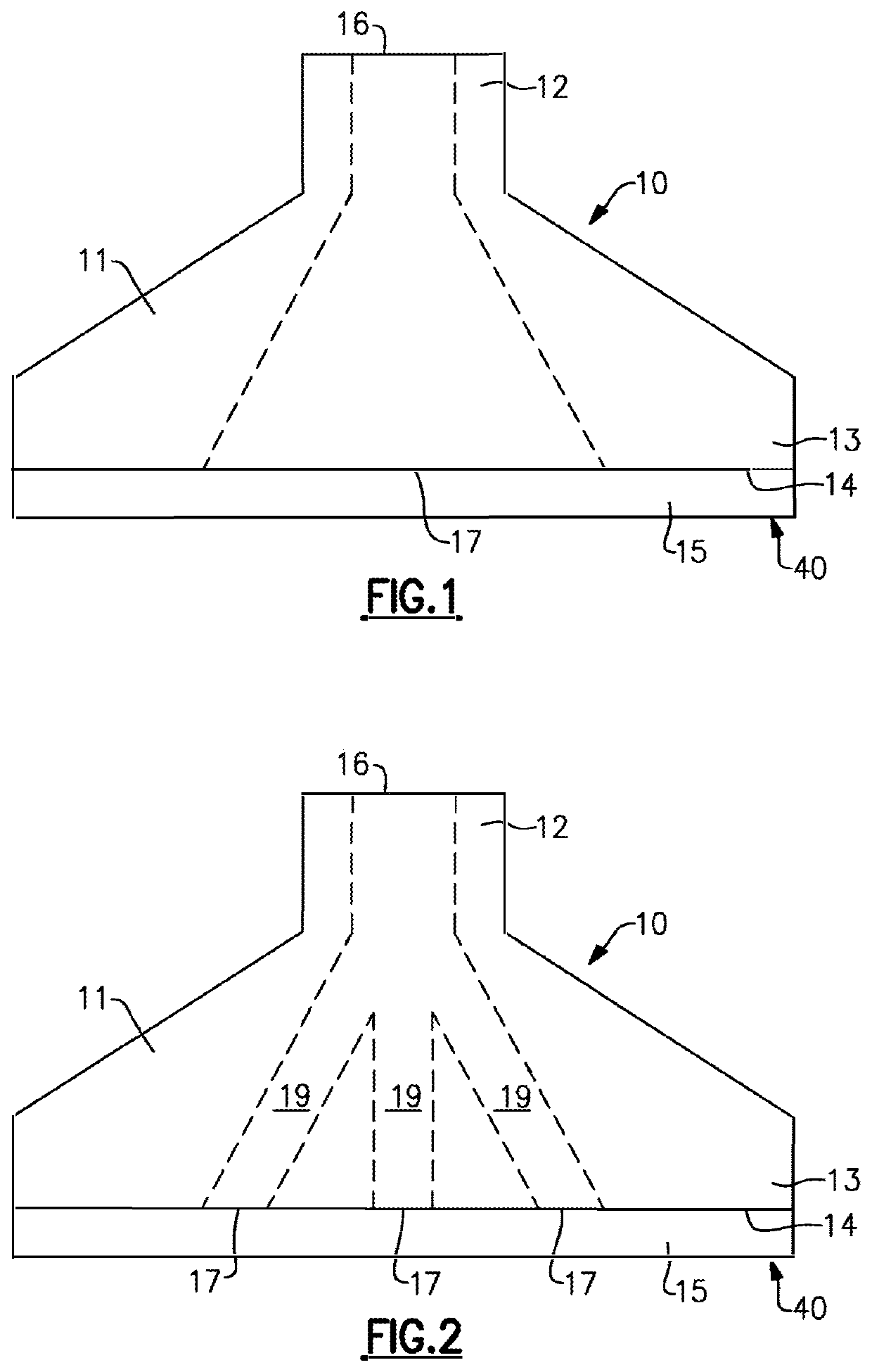
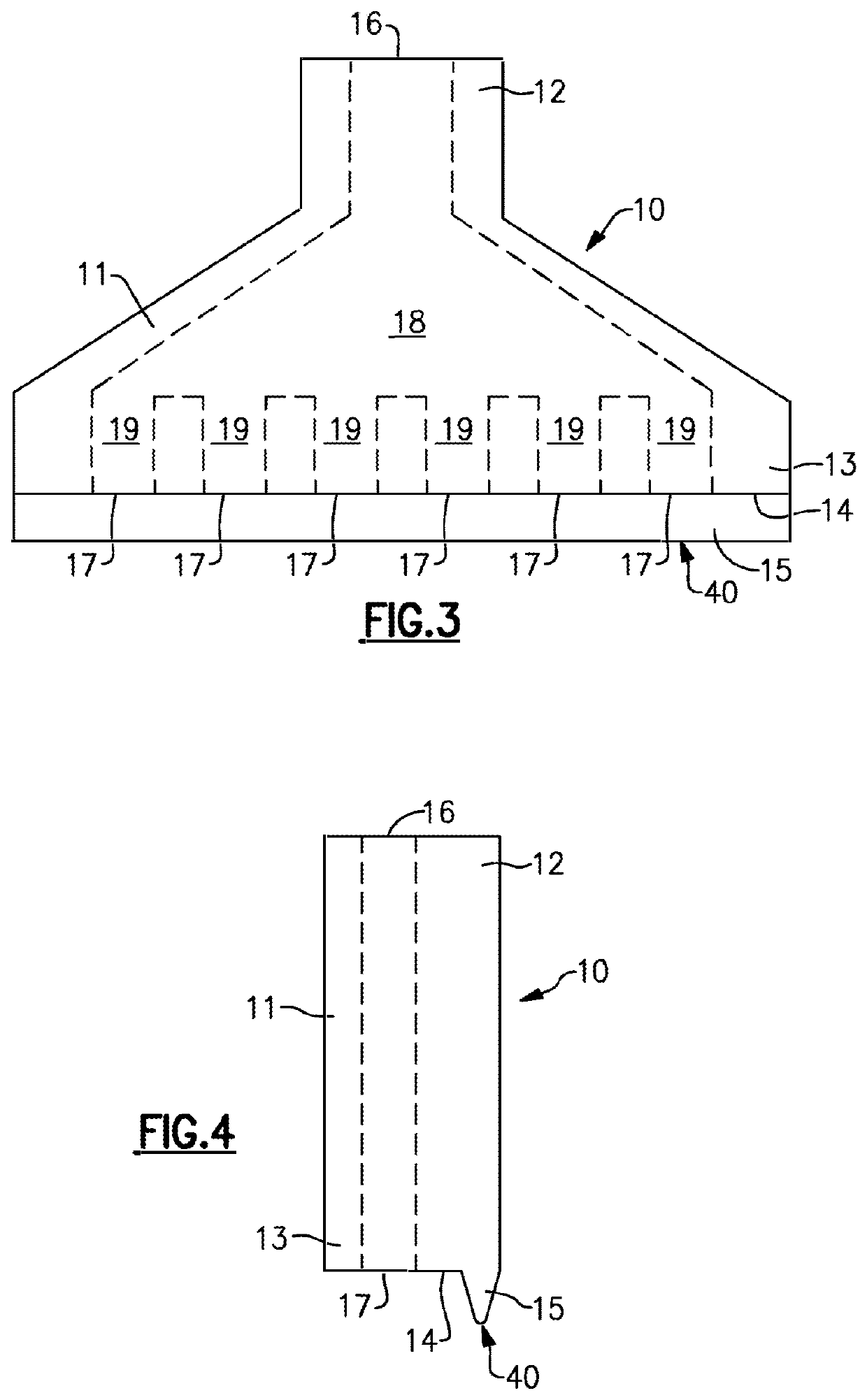
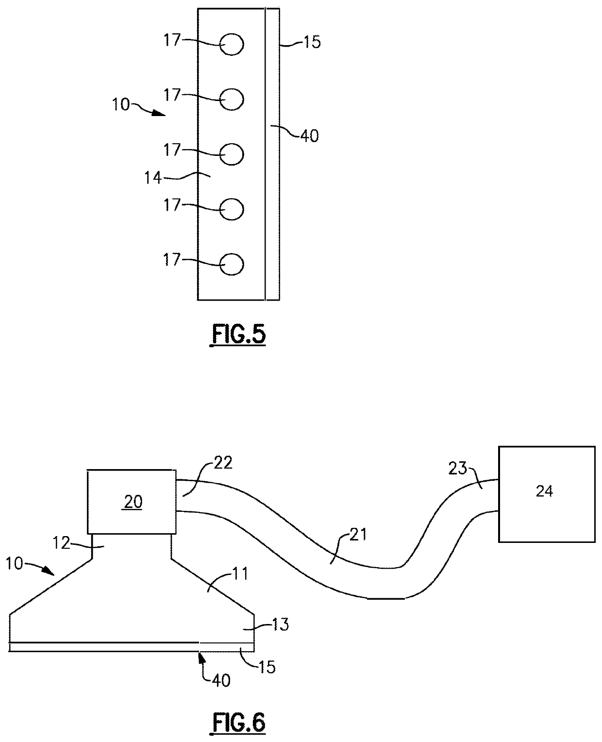
[0052]A specific embodiment of the squeegee apparatus of the invention is shown in FIGS. 9-13. In the embodiment shown in these figures, the lip member 15 has a length of 1.48 inches and an overall height of the squeegee apparatus 10 from the edge 40 to the inlet opening 16 is 1.40 inches. The entirety of the squeegee apparatus 10 depicted in FIGS. 9-13 is made from isobornyl acrylate. The following Table 1 provides material properties of this embodiment of the squeegee apparatus.

[0053]

TABLE 1ASTMUNITSMETRICUNITSIMPERIALTensile strengthD-412MPa0.8-1.5Psi115-220Elongation atD-412%170-220%170-220breakCompressive setD-395%4-5%4-5Shore HardnessD-2240Scale A26-28Scale A26-28(A)Tensile TearD-624Kg / cm2-4Lb / in18-22resistancePolymerizedASTMg / cm31.12-1.13densityD792

[0054]Other embodiments of the squeegee apparatus will differ from the embodiment of Example 1. For example, other embodiments of the squeegee apparatus may differ in materials used, shape, number and orientation of outlet openings...


PUM

PropertyMeasurementUnit
shore hardnessaaaaaaaaaa
densityaaaaaaaaaa
tensile strengthaaaaaaaaaa

Abstract

The present invention is directed to a squeegee apparatus which includes a main housing including an inlet end and an outlet end, the outlet end including an extrusion face and a protruding lip member, the inlet end including an inlet opening and the extrusion face including at least one outlet opening, wherein the inlet opening and the at least one outlet opening are in fluid communication with each other within the main housing. The present invention is also directed to a method for repairing a thermal barrier coating with a squeegee apparatus including supplying a repair composition into the inlet opening of the squeegee apparatus and depositing the repair composition from the at least one outlet opening onto the damaged region and concurrently traversing the squeegee apparatus over the damaged region while contacting a thermal barrier coating adjacent to the damaged region with the lip member.

Description

FIELD OF THE INVENTION[0001]The present invention is directed to a squeegee apparatus useful for dispensing and applying a coating repair composition. The present invention is also directed to a method of use of the squeegee apparatus disclosed herein.BACKGROUND OF THE INVENTION[0002]Higher operating temperatures of gas turbine engines are continually being sought in order to increase the efficiency of the engines. However, as operating temperatures increase, the high temperature durability of the components of the engine must correspondingly increase. Significant advances in high temperature capabilities have been achieved through the formulation of nickel, cobalt and iron based superalloys. These superalloys can be designed to withstand temperatures in the range of about 1000 to about 1100° C. or higher. Nonetheless, when used to form components of the turbine, such as combustor liners, augmentor hardware, shrouds and high and low-pressure nozzles and blades, the superalloys alone...

Claims


Application Information

Patent Timeline
Patent Type & Authority Patents(United States)
IPC IPC(8): B05C11/04B05C17/00B22F7/08B22F5/00B05C11/02B05C5/02
CPCB22F5/009B05C17/002B05C11/023B22F7/08B05C11/045B05C5/027B05C11/04
Inventor KUO, PEI-HSINGRIFFIN, WESTON BLAINEVENKATARAMANI, VENKAT SUBRAMANIAMKESHAVAN, HRISHIKESH
Owner GENERAL ELECTRIC CO
Why Eureka
Try Eureka