Diffuser particle separator

a technology of diffuser air and separator, which is applied in the direction of machines/engines, mechanical apparatus, liquid fuel engines, etc., can solve the problems of reducing the compliance of the tbc micro-structure, reducing the effectiveness of cooling, oxidation and thermal-mechanical fatigue,

Inactive Publication Date: 2009-09-01
HONEYWELL INT INC
View PDF17 Cites 53 Cited by
  • Summary
  • Abstract
  • Description
  • Claims
  • Application Information

AI Technical Summary

Problems solved by technology

Corrosive dust and salt particle deposits may be responsible for hot corrosion in the turbine and blockage of air-cooling passages (effusion cooling holes) in the combustion liner and internal cooling passages in turbine airfoils.
These small cooling holes can plug with dust particles, reducing the effectiveness of the cooling and causing oxidation and thermal-mechanical fatigue.
The dust particles may melt and wick into the TBC, reducing the compliance of the TBC micro-structure.
The result may be spallation of the TBC coating which may elevate the airfoil metal temperatures and cause oxidation and thermal-mechanical fatigue distress.
The '552 patent, however, does not disclose apparatus or methods for removing particles from an air flow within the diffuser or at the exit of the diffuser.
The '049 patent, however, does not disclose apparatus or methods for removing particles from an air flow within or at the exit of the diffuser.

Method used


Image

  • Diffuser particle separator
  • Diffuser particle separator
  • Diffuser particle separator

Examples


Embodiment Construction

[0017]The following detailed description is of the best currently contemplated modes of carrying out the invention. The description is not to be taken in a limiting sense, but is made merely for the purpose of illustrating the general principles of the invention, since the scope of the invention is best defined by the appended claims.

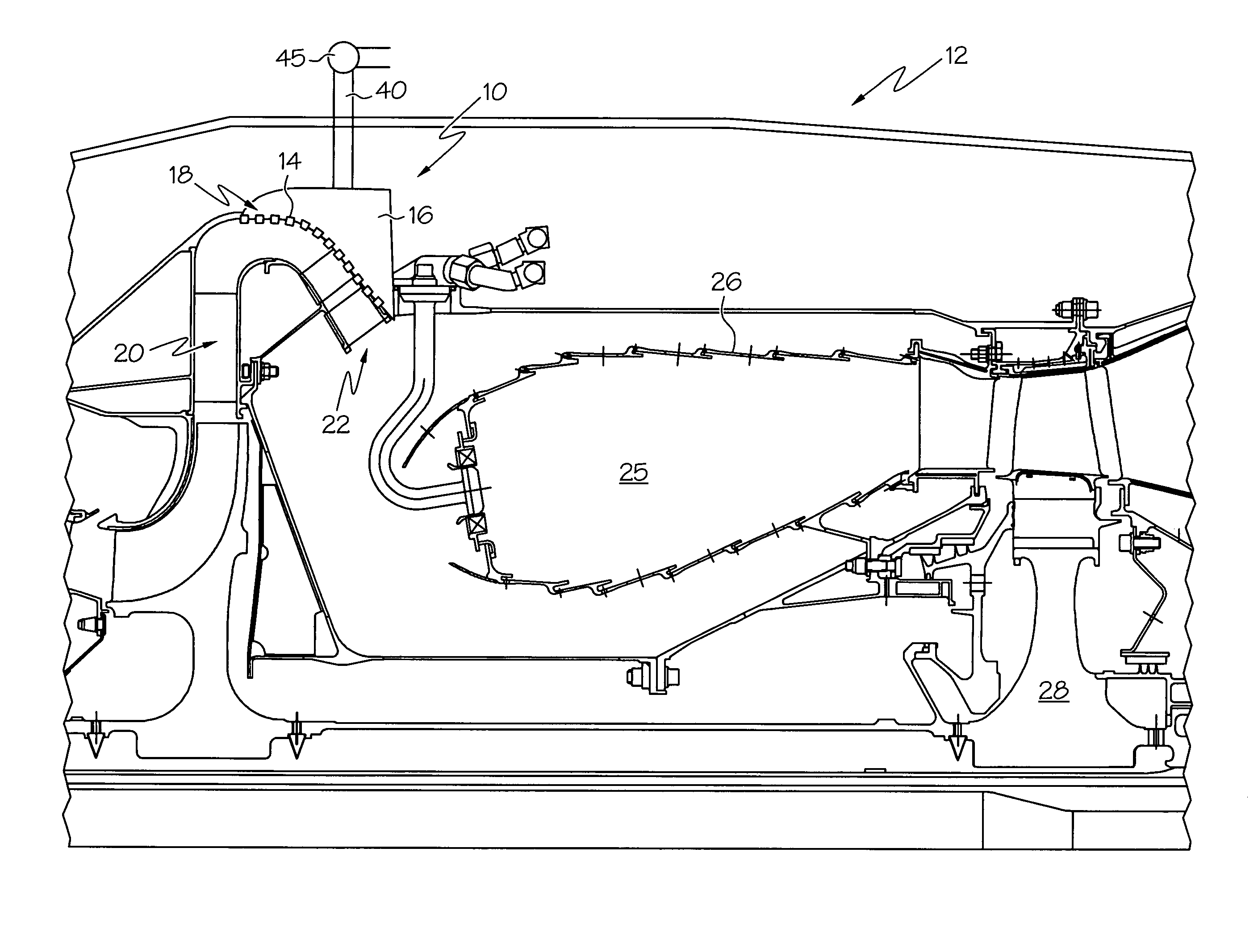
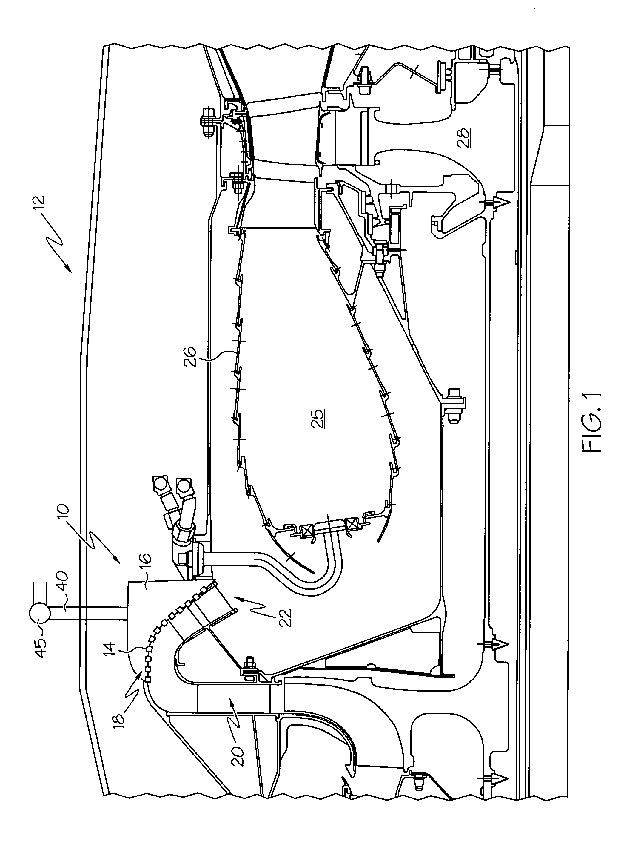
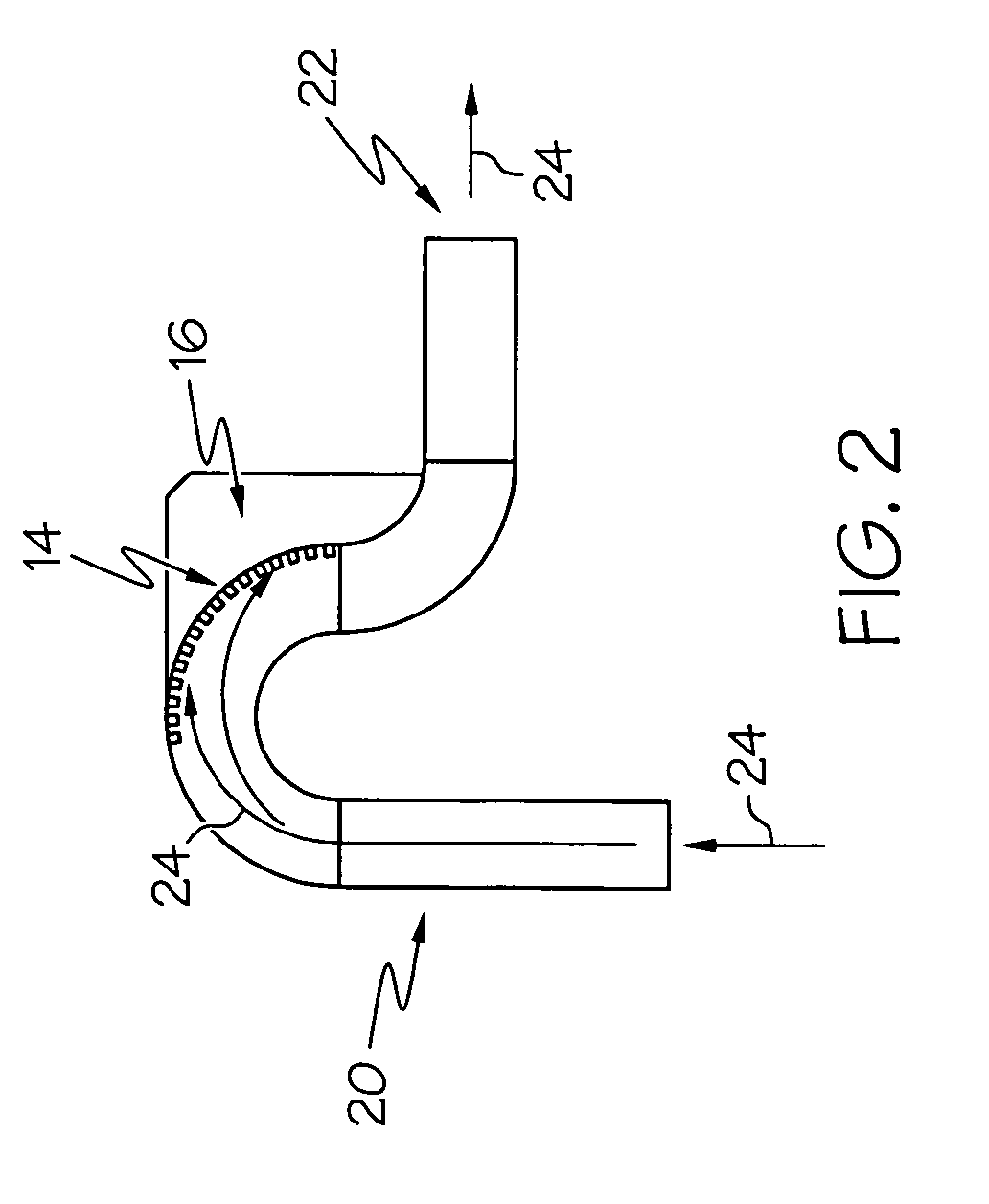
[0018]Broadly, the present invention provides an inertial and / or electronic particle separator located in a diffuser or at the exit of a diffuser of a gas turbine engine. The diffuser particle separator may capture and remove salt and dust particles from the core airflow. This efficient means of dust collection may improve component environmental life while reducing thermal-mechanical fatigue distress on components such as the combustion liner and turbine airfoils. The apparatus of the present invention may be useful on any turbine engine, including those found in aircraft, ground vehicles, generators and other industrial gas turbine engines.

[0019]Unlik...


PUM


Abstract

A diffuser particle separator may be integrated into a gas turbine engine to remove corrosive dust and salt particles from the engine's core air flow. The air flow may pass over a series of particle accumulator entrance orifices, trapping particles in a particle accumulator while allowing the air flow to continue unimpeded. Since dust deposits may become molten at high temperatures, removal of dust from the core and secondary airflow may be critical for long-life superalloy and ceramic components, particularly those with small diameter air-cooling holes and thermal barrier coatings.

Description

BACKGROUND OF THE INVENTION[0001]The present invention generally relates to apparatus and methods for providing clean core air in an engine and, more specifically, to apparatus and methods for separating particles from diffuser air.[0002]Corrosive dust and salt particle deposits may be responsible for hot corrosion in the turbine and blockage of air-cooling passages (effusion cooling holes) in the combustion liner and internal cooling passages in turbine airfoils. Removal of dust from the core airflow is required to significantly improve turbine and combustor durability.[0003]For example, as turbine inlet temperatures continue to increase to improve the efficiency of modern gas turbine engines, a large number of small cooling holes are required along combustor liners and turbine airfoils to cool the components. These small cooling holes can plug with dust particles, reducing the effectiveness of the cooling and causing oxidation and thermal-mechanical fatigue. Distress may also be o...

Claims


Application Information

Patent Timeline
Patent Type & Authority Patents(United States)
IPC IPC(8): F02C1/00F02G3/00F03B11/08
CPCF04D29/441F04D29/701F05B2260/63
Inventor STRANGMAN, THOMAS E.MORRIS, MARK C.BAKER, WILLIAM C.KINGTON, HARRY L.
Owner HONEYWELL INT INC
Why Eureka
Try Eureka