
Diffusion barrier and protective coating for turbine engine component and method for forming

a technology of turbine engine and barrier layer, which is applied in the direction of machines/engines, plasma techniques, natural mineral layered products, etc., can solve the problems of reducing the ability of the outer region to regenerate the protective alumina layer, preventing the formation of an adequate protective alumina layer, and undesirably consuming a portion of the wall

Inactive Publication Date: 2005-04-14
GENERAL ELECTRIC CO +1
View PDF29 Cites 55 Cited by
  • Summary
  • Abstract
  • Description
  • Claims
  • Application Information

AI Technical Summary

Problems solved by technology

This reduction in concentration will reduce the ability of the outer region to regenerate the protective alumina layer.
Moreover, the aluminum diffusion can result in the formation of a diffusion zone in an airfoil wall, which undesirably consumes a portion of the wall.
Simultaneously, migration of the traditional alloying elements like molybdenum and tungsten from the substrate into the coating can also prevent the formation of an adequately protective alumina layer.
However, very thin layers of some materials may be insufficient for reducing the interdiffusion at high operating temperatures.
Otherwise, the overlying coating may spall during thermal cycling of the turbine engine component.

Method used


Image

  • Diffusion barrier and protective coating for turbine engine component and method for forming
  • Diffusion barrier and protective coating for turbine engine component and method for forming

Examples


example

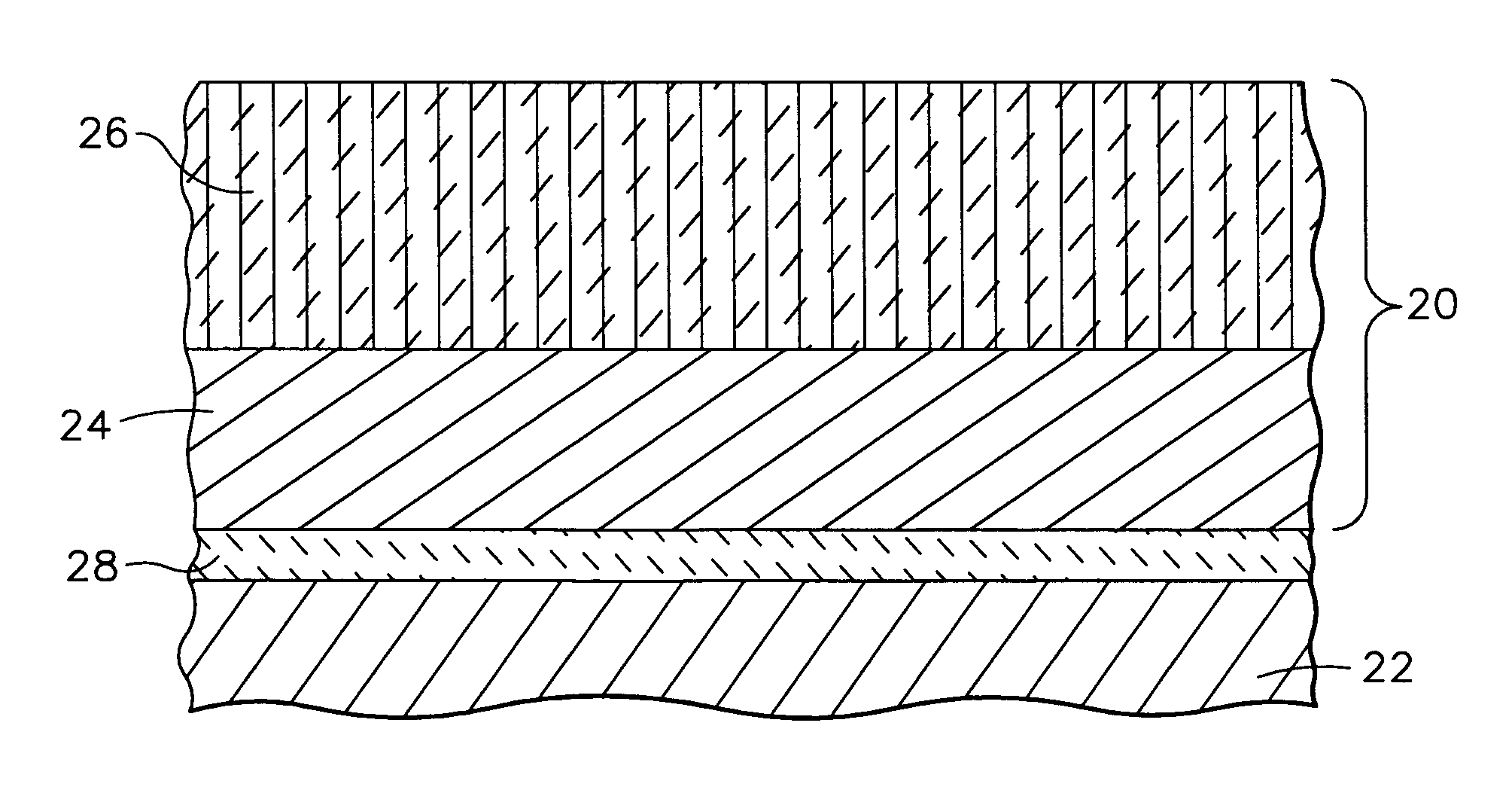
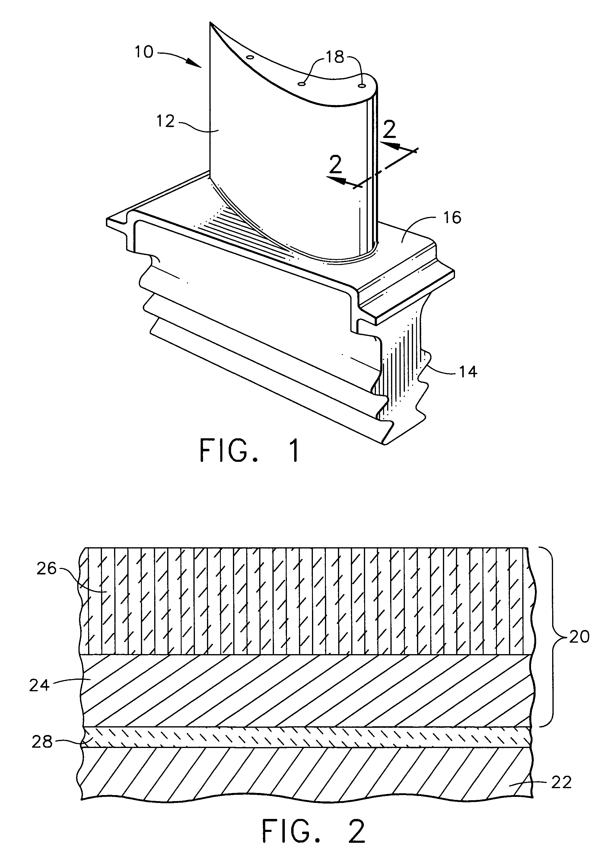
[0052] A protective coating system of the invention comprising a diffusion barrier layer and a protective coating is formed on button specimens of a nickel-base superalloy known as René N5 having a nominal composition, in weight percent, of 7.5% Co, 7.0% Cr, 6.2% Al, 6.5% Ta, 5.0% W, 3.0% Re, 1.5% Mo, 0.15% Hf, 0.05% C, 0.004% B, 0.01% Y, with the balance nickel and incidental impurities. First, an aluminum oxide diffusion barrier layer about 1 micron thick is formed on the substrate by oxidizing the surface of the aluminum rich superalloy. The oxidation step is performed by heating the substrate to a temperature in the range of from about 900° C. to about 1150° C. for about two hours in air or in a controlled atmosphere, especially with a partial pressure of oxygen.

[0053] A thin flash layer (about 2 microns thick) of platinum is applied over the diffusion barrier layer by sputtering. Layers of platinum (about 76.2 microns thick), rhodium (about 12.7 microns thick), and palladium (...


PUM

PropertyMeasurementUnit
Temperatureaaaaaaaaaa
Timeaaaaaaaaaa

Abstract

A turbine engine component comprising a substrate made of a nickel-base or cobalt-base superalloy, a non-metallic oxide or nitride diffusion barrier layer overlying the substrate, and a protective coating overlying the barrier layer, the protective coating comprising at least one platinum group metal selected from the group consisting of platinum, palladium, rhodium, ruthenium and iridium. The diffusion barrier layer may be a deposited or thermally grown oxide material, especially aluminum oxide. The protective coating may be heat treated to increase homogeneity of the coating and adherence with the substrate. The component typically further comprises a ceramic thermal barrier coating overlying the protective coating. Also disclosed are methods for forming a protective coating system on the turbine engine component by forming the non-metallic oxide or nitride diffusion barrier layer on the substrate and then depositing the platinum group metal on top of the barrier layer.

Description

BACKGROUND OF THE INVENTION [0001] The present invention relates to a diffusion barrier layer and protective coating for turbine engine components that are exposed to high temperature, oxidation and corrosive environments. More particularly, the invention is directed to forming a non-metallic oxide or nitride diffusion barrier layer between a superalloy substrate and a protective coating for the substrate. The protective coating can be an environmental coating or a bond coat for a thermal barrier coating on the turbine engine component, and is formed by depositing at least one platinum group metal on the diffusion barrier layer. [0002] In aircraft gas turbine engines, the turbine vanes and blades are typically made of nickel-based or cobalt-based superalloys that can operate at temperatures of up to about 1150° C. Various types of coatings are used to protect these superalloys. One type of protective coating is based on a material like MCrAl(X), where M is nickel, cobalt, or iron, o...

Claims


Application Information

Patent Timeline
IPC IPC(8): C23C4/02C23C4/18C23C28/00C25D5/34C25D5/48F01D5/28
CPCC23C4/02C23C28/36C23C28/345C23C28/3455C25D5/34C25D5/48F01D5/288Y02T50/67F05D2300/21F05D2300/228F05D2230/90F05D2300/143F05D2300/611F05D2300/22F05D2300/2118F05D2300/2112F05D2300/2281C23C28/322C23C4/18Y02T50/60
Inventor GORMAN, MARK DANIELNAGARAJ, BANGALORE ASWATHADAROLIA, RAMGOPAL
Owner GENERAL ELECTRIC CO
Learn More