Antenna assembly for vehicle

a technology for antennas and vehicles, applied in the direction of collapsible antennas, non-resonant long antennas, coupling device connections, etc., can solve the problems of low reception performance and deterioration of productivity, and achieve the effect of improving productivity and uniform manufacturing

Active Publication Date: 2020-05-19
HYUNDAI MOTOR CO LTD +1
View PDF8 Cites 0 Cited by
  • Summary
  • Abstract
  • Description
  • Claims
  • Application Information

AI Technical Summary

Benefits of technology

[0029]The antenna assembly for a vehicle may further include: a side hole bored from the external circumference of the external part to the hollow; a side protrusion gradually protruded in a downward direction from an external circumference of the internal part to be inserted into the side hole; and an escape prevention groove disposed wherein the side protrusion is positioned therein and formed along an internal circumference of the pin insertion groove wherein interference with the side protrusion by the rotation of the rotating pin is prevented.
[0032]According to an exemplary embodiment of the present invention, productivity can be improved as uniform manufacturing is possible irrespective of mounting positions by rotating the wire connector to be applicable to all cases of mounting on the left or right side of a roof.

Problems solved by technology

Among the antennae, the manual type of antenna is disadvantageous in terms of external appearance because it is exposed to the outside of the vehicle, and the glass type of antenna has a drawback in that receiving performance thereof is low.
That is, productivity may be deteriorated as the micro type antenna which is mounted on the left side of the roof and the micro type antenna which is mounted on the right side of the roof are respectively manufactured to have a different extending direction of a connector coupling a terminal with a power wire.

Method used


Image

  • Antenna assembly for vehicle
  • Antenna assembly for vehicle
  • Antenna assembly for vehicle

Examples


Embodiment Construction

[0045]Reference will now be made in detail to various embodiments of the present invention(s), examples of which are illustrated in the accompanying drawings and described below. While the invention(s) will be described in conjunction with exemplary embodiments, it will be understood that the present description is not intended to limit the invention(s) to those exemplary embodiments. On the contrary, the invention(s) is / are intended to cover not only the exemplary embodiments, but also various alternatives, modifications, equivalents and other embodiments, which may be included within the spirit and scope of the invention as defined by the appended claims.

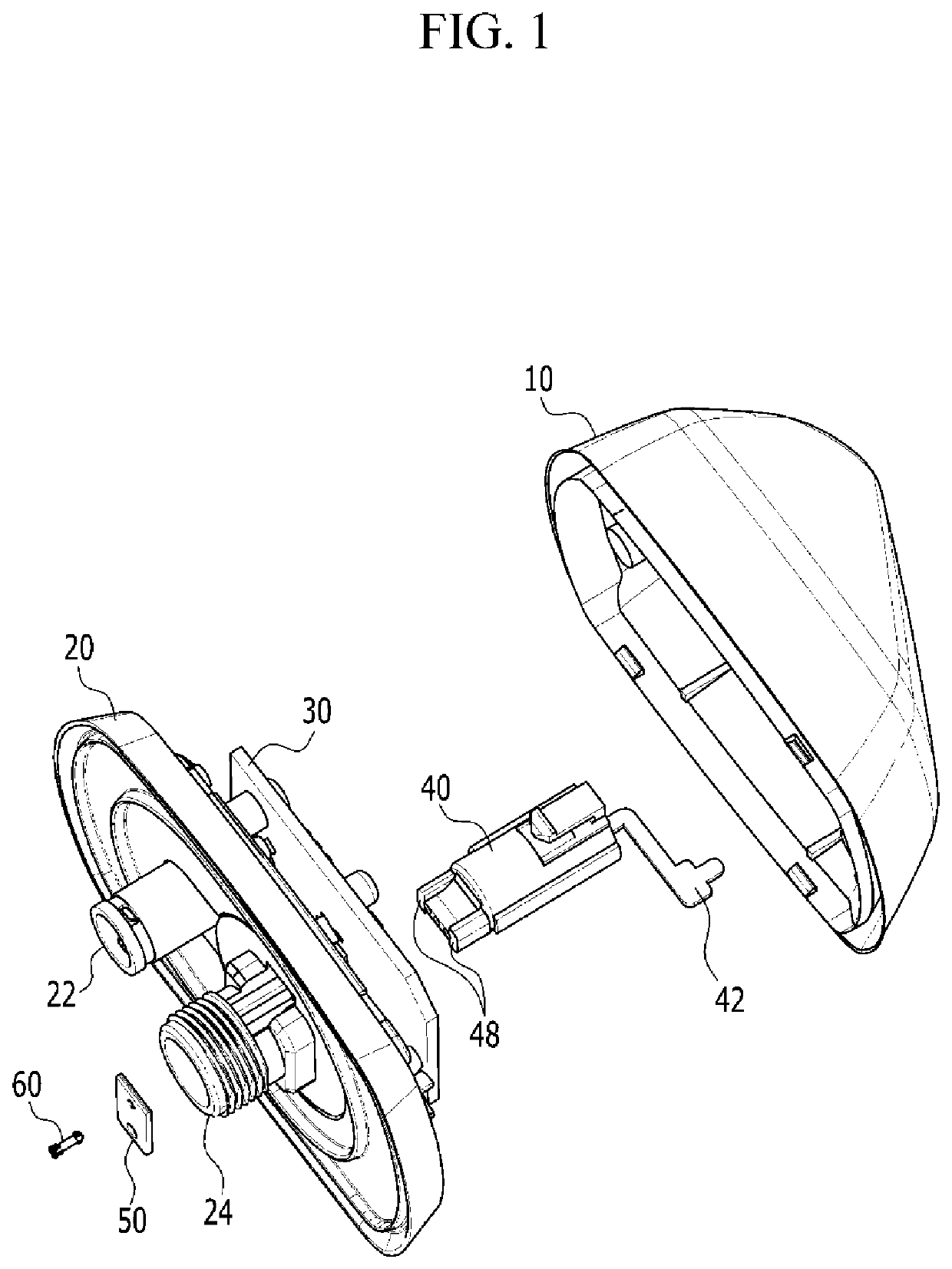
[0046]FIG. 1 is a schematic diagram of an antenna assembly for a vehicle according to an exemplary embodiment of the present invention.

[0047]As shown in FIG. 1, an antenna assembly for a vehicle according to an exemplary embodiment of the present invention includes a cover 10, a base 20, a circuit board 30, a terminal 40, a wire c...


PUM


Abstract

An antenna assembly for a vehicle may include: a cover into which a lower end portion of an antenna is inserted; a base coupled to a lower side of the cover to form an internal compartment; a circuit board mounted on an upper surface of the base to be connected to the lower end portion of the antenna; a terminal mounted to the base wherein an upper end portion thereof is connected to the circuit board and a lower end portion thereof penetrates into the base; a wire connector disposed at the lower end portion of the terminal to be connected to a power wire; and a rotating pin coupling the wire connector with the terminal, wherein the wire connector may be rotatable about the rotating pin.

Description

CROSS-REFERENCE(S) TO RELATED APPLICATIONS[0001]The present application claims priority to Indian Patent Application 201811002489, filed on Jan. 22, 2018, the entire contents of which is incorporated herein for all purposes by this reference.BACKGROUND OF THE INVENTIONField of the Invention[0002]The present invention relates to an antenna assembly for a vehicle. More particularly, the present invention relates to an antenna assembly for a vehicle capable of improving freedom of design.Description of Related Art[0003]Generally, antennae for a vehicle may be currently classified into a manual type of antenna, a glass type of antenna, a micro type of antenna, and the like.[0004]Among the antennae, the manual type of antenna is disadvantageous in terms of external appearance because it is exposed to the outside of the vehicle, and the glass type of antenna has a drawback in that receiving performance thereof is low. Accordingly, recently, the micro type of antenna has tended to be appli...

Claims


Application Information

Patent Timeline
Patent Type & Authority Patents(United States)
IPC IPC(8): H01Q1/32H01Q1/12H01R13/639H01R24/54H01Q1/08H01R24/40H01Q3/08
CPCH01Q1/08H01R24/40H01R24/545H01Q1/1214H01R13/639H01Q3/08H01Q1/3275H01R2201/02H01R2201/26H01Q11/08
Inventor JOSEPH, JACKHWANG, SEUNG HAILEE, JAEJUNVENKATA, AVINASH K.
Owner HYUNDAI MOTOR CO LTD
Why Eureka
Try Eureka